OP-ZのDMXをArudinoで使う

DMX機能を使ってみたいと思います。
こんな感じでライトなどをコントロールできます。
かっこいい!
マニュアル通りの正攻法で挑むとなるとDMXのインターフェースとDMX対応の灯体(照明器具そのもの)を買わないといけません。
灯体はピンキリで色々あるのでまだしも、インターフェースは公式対応しているENTTECのもので3万強します。。
ちょっと試してみたいくらいのモチベーションではなかなか手が出せない。ということで、表題のArduinoでどうにかしていきます。
Arduinoに挑む
購入当初よりアイデアとしてあったのですが、Arduino童貞であったこともあって、どう手をつけていいものか思案していたところ、op-forumsにて実践した方が現れました。
なるほど完全に理解(してない)
とりあえずゴールできることはわかったので、ものを揃えてみることに。
Arduino Unoを買ってしまう

フォーラムは何やらArduino Nanoでやってたのですが、こちとら童貞なのでやっぱUnoでしょ、とUnoを購入。
また光らせるLEDはNeoPixelというLEDが定番らしく、ひとまず試しにやすいものを購入。
とりあえずMake:の本も手に入れて、Arduino UnoでLチカなどを試してからDMXの連携をやってみました。
試行錯誤する
はんだごてで指を焼いたりしながら試行錯誤をします。なぜかうまくいかず。
単純にArduinoでNeoPixelをコントロールすることには成功していたので、OP-ZとArduinoの接続の問題とあたりをつけ、電源の供給方法ではないか、とUSBハブを手配しました。
Kingston Nucleumを買ってしまう

OP-Zがサポートを公表しているUSBハブを購入してしまいます。状況変わらず。よくよくフォーラムを読むと、シリアルUSB変換のチップがFTDI社製FT232RLでないとOP-Zが認識しないようです。
最初目を通した時にそれっぽいことは書いてあるな、と思ってはいたのですが、Arduino自体の理解がままならなかったので、クリティカルなことだと気付かず。折角の情報も知識がないと使えないのだな、としみじみ感じます。
完全に理解しArduino Nanoを買う

改めて完全に理解したので、Arduinoをはじめて4日で2台目のArduinoを手に入れました。これでようやくできる!と思いきやうまくいかず。。。詰んだ。。
結構本気で諦めるしかないか、と頭をよぎった時におもむろにArduino NanoとOP-Zを直結したら、、
うまくいかなかった原因はまさかのKingston Nucleumでした。これはArduinoとNucleumの問題なのかもしれないです。
手元にはつかうあてのない、Arduino UnoとNucleumが。
肝心のやり方
つい苦労話をしてしまいましたが、やり方を書きたかったことを思い出したので書きます。言わずもがなですが、いろいろと自己責任でお願いします。
用意するもの
OP-Z
→みんなだいすき
Arduino Nano
→互換品だと動かないかもなので注意
NeoPixelなどが載ったLEDモジュール
→直結で安定して光るのは4個が限度か。
USB-C to USB-mini Bケーブル
→要は変換できれば良いのですが相性等あるかも。自分のは以下。
パソコン
→コードを書き込むので
その他
→ArduinoとLEDモジュールをつなぐために、適宜ブレッドボードやら銅線やらジャンパワイヤやらはんだごてやら。
手順
1 ) IDEをインストールする。
まずはArduino IDEをインストールします。
https://www.arduino.cc/en/main/software
この辺の詳しい手順は山ほどあると思うので割愛。
2 ) ライブラリをインストールする。
IDEで二つのライブラリを使用します。
DMXUSB
https://github.com/DaAwesomeP/dmxusb
FastLED
https://github.com/DaAwesomeP/dmxusb
どちらもIDEのライブラリ管理から検索すると出てきます。
3 ) サンプルコードを編集
DMXUSBのサンプルコード「DMXUSB_FastLED」を編集します。
/* DMXUSB_FastLED.ino
 * Originally created 11/25/2017 by Perry Naseck (DaAwesomeP)
 * This is an example sketch for the DMXUSB Arduino/Teensy library to drive adressable LEDs with the FastLED library.
 * https://github.com/DaAwesomeP/dmxusb/
 *
 * Copyright 2017-present Perry Naseck (DaAwesomeP)
 *
 * Licensed under the Apache License, Version 2.0 (the "License");
 * you may not use this file except in compliance with the License.
 * You may obtain a copy of the License at
 *
 *    http://www.apache.org/licenses/LICENSE-2.0
 *
 * Unless required by applicable law or agreed to in writing, software
 * distributed under the License is distributed on an "AS IS" BASIS,
 * WITHOUT WARRANTIES OR CONDITIONS OF ANY KIND, either express or implied.
 * See the License for the specific language governing permissions and
 * limitations under the License.
 */

// The example uses code from the FastLED Blink example here:
// https://github.com/FastLED/FastLED/blob/master/examples/Blink/Blink.ino
// More information about FastLED here: https://github.com/FastLED/FastLED

#include "DMXUSB.h"
#include <FastLED.h>

// DMXUSB should receive and transmit data at the highest, most reliable speed possible
// Recommended Arduino baud rate: 115200
// Recommended Teensy 3 baud rate: 2000000 (2 Mb/s)
// DMX baud rate: 250000
// MIDI baud rate: 31250
#define DMXUSB_BAUDRATE 115200

// Number of LEDs on the strip
#define NUM_LEDS 1

// For LED chips like Neopixels, which have a data line, ground, and power, you just
// need to define DATA_PIN.  For LED chipsets that are SPI based (four wires - data, clock,
// ground, and power), like the LPD8806 define both DATA_PIN and CLOCK_PIN
#define DATA_PIN 3
#define CLOCK_PIN 13

// Define the array of LEDs
CRGB leds[NUM_LEDS];

// receive a DMX transmission
void showLEDs(int universe, char buffer[512]) {
  for (int index=0; index < 512; index++) { // for each channel, universe starts at 0
    int value = buffer[index]; // DMX value 0 to 255
    int LEDchannel = (universe*510) + index; // Find the LED number; can't fit a 3-channel fixture on the remaining two channels
    if (LEDchannel <= (NUM_LEDS*3)-1) { // If DMX channel (LEDchannel starts at 0) is in range of LEDs (3 channels per LED for RGB)
      int colorChannel = LEDchannel % 3; // Find the color channel of the LED addressed
      int ledID = (LEDchannel - colorChannel) / 3; // Find the FastLED index of the LED addressed
      if (colorChannel == 2) leds[ledID].r = value; // If the channel is red, write the red value of the LED
      if (colorChannel == 1) leds[ledID].g = value; // If the channel is green, write the red value of the LED
      if (colorChannel == 0) leds[ledID].b = value; // If the channel is blue, write the blue value of the LED
    }
  }
  FastLED.show(); // Display the frame after processing all channels
}

DMXUSB DMXPC(
  // Stream serial,
  Serial,
  // int baudrate,
  DMXUSB_BAUDRATE,
  // int mode,
  // With mode==1, the library processes two universes for a total of 1024 DMX channels
  1,
  // void (*dmxInCallback)(int universe, unsigned int index, char buffer[512])
  showLEDs
);

void setup() {
  Serial.begin(DMXUSB_BAUDRATE);

  // Uncomment/edit one of the following lines for your leds arrangement.
  // FastLED.addLeds<TM1803, DATA_PIN, RGB>(leds, NUM_LEDS);
  // FastLED.addLeds<TM1804, DATA_PIN, RGB>(leds, NUM_LEDS);
  // FastLED.addLeds<TM1809, DATA_PIN, RGB>(leds, NUM_LEDS);
  // FastLED.addLeds<WS2811, DATA_PIN, RGB>(leds, NUM_LEDS);
  // FastLED.addLeds<WS2812, DATA_PIN, RGB>(leds, NUM_LEDS);
  // FastLED.addLeds<WS2812B, DATA_PIN, RGB>(leds, NUM_LEDS);
  FastLED.addLeds<NEOPIXEL, DATA_PIN>(leds, NUM_LEDS);
  // FastLED.addLeds<APA104, DATA_PIN, RGB>(leds, NUM_LEDS);
  // FastLED.addLeds<UCS1903, DATA_PIN, RGB>(leds, NUM_LEDS);
  // FastLED.addLeds<UCS1903B, DATA_PIN, RGB>(leds, NUM_LEDS);
  // FastLED.addLeds<GW6205, DATA_PIN, RGB>(leds, NUM_LEDS);
  // FastLED.addLeds<GW6205_400, DATA_PIN, RGB>(leds, NUM_LEDS);

  // FastLED.addLeds<WS2801, DATA_PIN, CLOCK_PIN, RGB>(leds, NUM_LEDS);
  // FastLED.addLeds<SM16716, DATA_PIN, CLOCK_PIN, RGB>(leds, NUM_LEDS);
  // FastLED.addLeds<LPD8806, DATA_PIN, CLOCK_PIN, RGB>(leds, NUM_LEDS);
  // FastLED.addLeds<P9813, DATA_PIN, CLOCK_PIN, RGB>(leds, NUM_LEDS);
  // FastLED.addLeds<APA102, DATA_PIN, CLOCK_PIN, RGB>(leds, NUM_LEDS);
  // FastLED.addLeds<DOTSTAR, DATA_PIN, CLOCK_PIN, RGB>(leds, NUM_LEDS);
}

void loop() {
  DMXPC.listen();
}
LEDの数の変更
36行目、LEDの数を設定します。今回は8個です。
//Line 36
#define NUM_LEDS 8
色の修正
55行目、OP-Zの色のチャンネルに合わせるため、上からbrgに変更
//Line55
if (colorChannel == 2) leds[ledID].b = value; // If the channel is red, write the red value of the LED
if (colorChannel == 1) leds[ledID].r = value; // If the channel is green, write the red value of the LED
if (colorChannel == 0) leds[ledID].g = value; // If the channel is blue, write the blue value of the LED
使用しているLEDを修正
75行目から使用するLEDを設定します。デフォルトはNeoPixelになってますが、今回手に入れたものは、NeoPixel互換のWS2812Bだったため、それ以外のものを削除しました。(コメントアウトを切り替えるだけでもいい)
//Line75
void setup() {
  Serial.begin(DMXUSB_BAUDRATE);
  FastLED.addLeds<WS2812B, DATA_PIN, RGB>(leds, NUM_LEDS);
}
4 ) 書き込む
修正したコードをArduino Nanoに書き込みます。
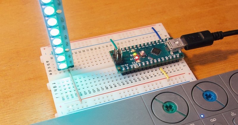
5 ) 繋ぐ
NeoPixelは5v、DATAIN、GNDがあるのでこれをどうにかして繋ぎます。
一番手軽なのは、両端がオスとメスのジャンパーワイヤを用意して、Arduino Nanoのピンヘッダにメスを刺し、オス側をはんだする感じかと思います。

作例としては、LEDにピンヘッダをはんだして、ブレッドボードで組む感じとしました。また3.3vで電源供給しています。こうすると私の環境では8個が安定して光らせることができました。
6 ) 電源オンして遊ぶ

DMXコントロールは右から2番目のライトトラックです。
改めて以外ガイド。
トラックリンクをつかうとサウンドエフェクトに連動してライトエフェクトをかけるとかできるぞ!
あとはもうArduinoなので、アイデア次第でビートに合わせて光る帽子とかサングラスとかつくったらいいと思います!
今後
LEDはもっと増やして遊ぶ方がきっと楽しいので、電力はACアダプタから供給する形に改良していきたいです。
その辺は多分Twitterやinstaにそのうち投稿するので、フォローしてね!
いただいたサポートは全て、アサヒスーパードライになります