TikZの私的基本

TikZの私的基本を書く。
コードの全体はこちらのOverLeafでご確認ください。
=> 最下部に貼りました.(Feb. 3rd, 2020)
基本
TikZでは,pathとnodeで絵を描きます。
pathについて
pathに日本語をあてると,経路です。例えば,点(0, 0)と点(1, 1)を結べば2点を結ぶpathができます。TikZでは,以下のように書きます。
\path (0, 0) -- (1, 1); 作ったpathにオプションを指定することで,いろいろな操作ができます。例えば,オプションにdrawを指定すると,作ったpathを描きます。オプションは,[]の中に書きます。
\path[draw] (0, 0) -- (1, 1);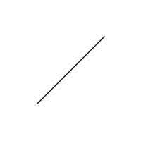
nodeについて
nodeに日本語をあてると,節です。nodeはpathの途中におきます。例えば,点(0, 0)と点(1, 1)を結ぶpathの終点にnodeを置くには,以下のように書きます。
\path[draw] (0, 0) -- (1, 1) node {};{}の中にテキストを書くと,nodeの位置にテキストを表示します。
\path[draw] (0, 0) -- (1, 1) node {hogehoge};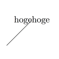
nodeにオプションを指定すると,nodeに対する操作ができます。例えば,nodeを座標の5mm右側に配置し,長方形で囲むには,以下のように書きます。
\path[draw] (0, 0) -- (1, 1) node[right=5mm, draw] {hogehoge};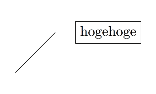
nodeに配置するテキストがないときも,{}は必要で,省くとエラーになります。
以上のようなpathとnodeの概念を基本として,
「どのようにpathを作るか」
「作ったpathに何をするか」
「どのようにnodeを配置するか」
「配置したnodeに何をするか」
などを考えて,様々な絵を描きます。
いくつかの例
\path[draw] (0, 0) node[fill, color=magenta] {} -- (1, 0) node[fill, circle, color=cyan] {} -- (2, 0) node[fill, color=yellow] {};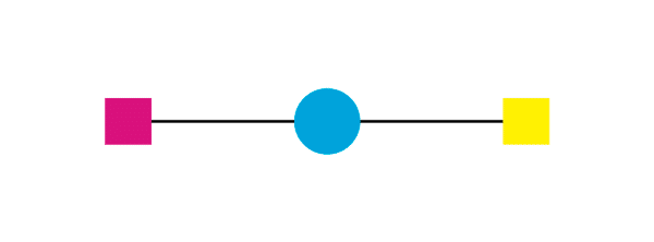
%
%  (A)という名前のnodeを(0, 0)に配置する。
%
\path node[circle, draw] (A) at (0, 0) {A};
%
%  (B)という名前のnodeを(1, 1)に配置する。
%
\path node[circle, draw] (B) at (1, 1) {B};
%
%  (A)と(B)を結ぶpathを作り,drawする。
%
\path[draw] (A) -- (B);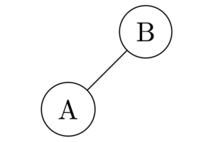
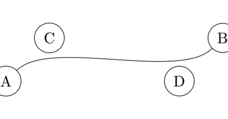
\path node[circle, draw] (A) at (0, 0) {A};
\path node[circle, draw] (B) at (5, 1) {B};
\path node[circle, draw] (C) at (1, 1) {C};
\path node[circle, draw] (D) at (4, 0) {D};
%
%  ベジェ曲線の利用
%
\path[draw] (A) .. controls (C) and (D) .. (B);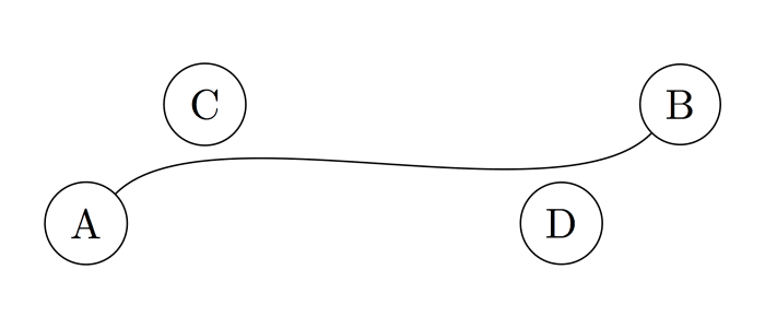
以下,TeXソースです.
\RequirePackage{luatex85}
\documentclass{ltjsarticle}
\usepackage{tikz}
\usepackage{luatexja}
\begin{document}
\begin{verbatim}
 \path (0, 0) -- (1, 1);
\end{verbatim}
\begin{tikzpicture}
 \path (0, 0) -- (1, 1);
\end{tikzpicture}

\begin{verbatim}
 \path[draw] (0, 0) -- (1, 1);
\end{verbatim}
\begin{tikzpicture}
 \path[draw] (0, 0) -- (1, 1);
\end{tikzpicture}


\begin{verbatim}
 \path[draw] (0, 0) -- (1, 1) node {};
\end{verbatim}
\begin{tikzpicture}
 \path[draw] (0, 0) -- (1, 1) node {};
\end{tikzpicture}

\begin{verbatim}
 \path[draw] (0, 0) -- (1, 1) node {hogehoge};
\end{verbatim}
\begin{tikzpicture}
 \path[draw] (0, 0) -- (1, 1) node {hogehoge};
\end{tikzpicture}

\begin{verbatim}
 \path[draw] (0, 0) -- (1, 1) node[right=5mm, draw] {hogehoge};
\end{verbatim}
\begin{tikzpicture}
 \path[draw] (0, 0) -- (1, 1) node[right=5mm, draw] {hogehoge};
\end{tikzpicture}

\begin{verbatim}
 \path[draw] (0, 0) node[fill, magenta] {} -- (1, 0) node[fill, circle, color=cyan] {} -- (2, 0) node[fill, color=yellow] {};
\end{verbatim}
\begin{tikzpicture}
 \path[draw] (0, 0) node[fill, magenta] {} -- (1, 0) node[fill, circle, color=cyan] {} -- (2, 0) node[fill, color=yellow] {};
\end{tikzpicture}

\begin{verbatim}
 \path node[circle, draw] (A) at (0, 0) {};
 \path node[circle, draw] (B) at (1, 1) {};
 \path[draw] (A) -- (B);
\end{verbatim}
\begin{tikzpicture}
 % (A)という名前のnodeを(0, 0)に配置する。
 \path node[circle, draw] (A) at (0, 0) {};
 % (B)という名前のnodeを(1, 1)に配置する。
 \path node[circle, draw] (B) at (1, 1) {};
 % (A)と(B)を結ぶpathを作り,drawする。
 \path[draw] (A) -- (B);
\end{tikzpicture}

\begin{verbatim}
 \path node[circle, draw] (A) at (0, 0) {A};
 \path node[circle, draw] (B) at (5, 1) {B};
 \path node[circle, draw] (C) at (1, 1) {C};
 \path node[circle, draw] (D) at (4, 0) {D};
 \path[draw] (A) .. controls (C) and (D) .. (B);
\end{verbatim}
\begin{tikzpicture}
 \path node[circle, draw] (A) at (0, 0) {A};
 \path node[circle, draw] (B) at (5, 1) {B};
 \path node[circle, draw] (C) at (1, 1) {C};
 \path node[circle, draw] (D) at (4, 0) {D};
 \path[draw] (A) .. controls (C) and (D) .. (B);
\end{tikzpicture}
\end{document}お役に立ったらスキしてください. サポートは投稿を続けるモチベーションになります. ありがとうございます.