Maker Faire Tokyo 2023 応募へ向けて

Maker Faire Tokyo 2023へ出展申請を予定しております。事務局様への参考資料を兼ねてこれまでの経緯などを以下にまとめます。
内容 1,出展物 2,概略説明 3,MakerFaireへの出展経験
1,出展物 ESP32とCCDを利用した自作分光計の農業への応用例
2,概略説明 申請者は結晶、セラミック、金属などの受託加工業をしております。また、製品に水晶振動子をもちいた微小重量センサQuartz Crystal Microbalance (QCM)があります。このQCMと分光計を組み合わせた分析機器の開発をしていました。 小型の機器を志向したので、分光計も小型のものを検討することになりました。
小型分光計は1970年代に開発が始まっているようです。Ocean社の製品が知られています。また、MEMS利用のハマホト社の製品も広く利用されています。 ただ、価格面と仕様面から内製することになりました。
分光計の内製を模索する中で、光学系、センサ回路、データ処理、PC等のUI、に課題を分け、ざっくり、光学と回路の2つを解決する必要があることがわかりました。このあと紆余曲折があり、動作モデルが実現しました。
ありがちな話で、試作品の完成を喜んだのも束の間、分析機器のプロジェクトは頓挫し、終了してしまいました。一方で、せっかく作ったものを一人で後生大事に抱えていても仕方がありません。分光器に興味がある方は世の中にきっといると考え、製作過程や動作原理を公表することで、役立つこともあるのではないかと思い、発表活動をしています。
そこで、広くニーズを知るために、学会への参加、Kickstarter、Publab、SNSへの投稿、をおこなってきました。MakerFaireもニーズ収集の一端なのですが、電子関係や自作に詳しい方が多数来訪されるのと、日常業務の解決案(具体的には塗膜の色彩や厚み、化学反応、位置計測など)を探りつつ余暇を楽しむ方に出会えることがわかりましたので、継続して出展申請をおこなっております。
今回はSendaiMMF2022に出展した際に、計測・解析ラボの大橋さんも出展されいたご縁で、LabVIEWアプリケーションと分光器(ラインCCD)の制御という内容で、コラボレーションをお願いしたところ、快諾いただきました。従来の動作アプリではなく、LabVIEWアプリケーションを新規作成し、改変可能なアプリを無償配布で公開しました。
LabVIEWアプリケーションが追加されたことが新しい点です。分光器の光学系、リニアセンサの駆動回路はこれまでのエントリと同様のものを使用しています。
以下にリンクを貼っておきます。
==================================
以下にKickstarterへの投稿を示します。
DIY Spectrometer
Motivation: We are dealing with piezo crystal products. We are considering new analysis technique that combining piezo sensor and spectrometer measurements. However, commercially available multichannel spectrometer is very expensive, $2,000-$4,000 . So we decided to develop by our self.

System : In the measurement system, connect the PC and spectrometer via USB, and measurement software perform data acquisition and graph display.
Data can be saved as a text (csv) file.
In addition, initial calibration is performed at the time of manufacturing and shipping, it is possible for users to recalibrate easily.
Filters and slits can be changed arbitrarily by the user depending on the wavelength and intensity of light.


The spectrometer uses mirrors and diffraction gratings. The photograph shows that a spectrum with incidence of a Hg lamp. You can see green, blue and purple on the right side of the screen.

Calibration :
1, Pre-measurement is occurred to using Hg lamp* . Software using dummy Pixel No. and wave length. *Hg-Ar is better.
2, Result of pre-measurement gives true pixel No. and wave length.
3, To overwrite a calibration file. (column A; pixel No., column B wave length)


Structure : The internal structure consists of a spectroscope, a CCD sensor, and a PCB substrate.
Contents :
-Spectrometer (slit, filter : customer’s choice) x1
-Software (English or Japanese) x1
-Hex wrench x1
RISK
This spectrometer is easy to used but technical. We hope that you are interested in physics, biochemistry, DIY. Our project has a number of risks as below:
1) It does not compensate for the complete operation of electronic circuits and software.
2) We will not compensate for any damage, accidents, injuries etc due to using this drawing and software.
*Regarding downloading of the files, we regard it as approved for the above risks and we will not indemnify anything.
==================================================
publiclab への投稿
DIY-spectrometer episode 2 (using LEGO)
by TakeshiMatsumoto | April 11, 2018 08:58 | #16130
Background;
We launched DIY-spectrometer three weeks ago. This product was supposed to be used by experts who can treat special optics and tuning by oneself. However, there was a problem from the viewpoint of making a spectrometer by oneself, because of the product was made of aluminum enclosure and used some optical components. So we tried making a spectrometer using LEGO to focus on DIY.
Purpose;
1, For beginners, easy to assembling and to obtaining accurate results.
2, For researchers, we offer a low cost spectrometer for preliminary experiments. Also make it available for workshops like public lectures.
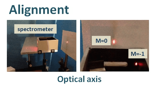
Optical System;

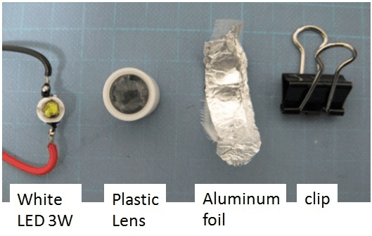
Parts;
LEGO

*Of course you need top cover, using same parts of Base.
If you use liner ccd, need to back wall and completely light shield.
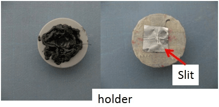
Optics

Slit

Light source
Assembling;
Front

Side

Top

Back

*Caution; Turn off the LEDs! In case of seeing the grating from the back. Strong light will hurt your eyes.
Experiment;


Data analysis;
1. Using photograph, take a picture by Rasp PI camera, Cell phone, Digital camera etc.
2. Using Liner sensor, Tohshiba, SONY, HAMAMATSU etc.

Notice;
1. Protect your eyes when using strong LEDs.
2. I intentionally use strong LEDs so that diffracted light can be understood well even in indoor lighting in this time. When you detect this light with a CCD it will be saturate immediately.
3. In order to reduce light reflection and scattering, it is effective to stick a black cloth on the inside.
4. It is better to seal from the gap of the block to prevent light from entering.
Safety first and Enjoy!
※ミラーと回折格子の位置を調整していませんので、回折光のパターンがUV→VIS→NIRのようになっておりません。この点は調整可能です。
3,過去の出展経験 個人として参加しております。Tsukuba Mini Maker Faire 2020、Maker Faire Tokyo 2020、SendaiMMF2022、OgakiMMF2022 4の回です。
【Tsukuba Mini Maker Faire 2020】
想像よりお客様は多い。中学生のロボコンもあるらしい。#tmmf pic.twitter.com/8gIBU2edum
— 松元健@モノづくり~IoTxAIへ (@Takeshi_Matsu12) February 15, 2020
【Maker Faire Tokyo 2020】
無事終了。大変お世話になりました。来年も開催されますように。#MakerFaireTokyo2020 pic.twitter.com/O8vHDDhkKh
— 松元健@モノづくり~IoTxAIへ (@Takeshi_Matsu12) October 4, 2020
【SendaiMMF2022】
#SendaiMMF 久々の対面展示。出展者の方々と有意義なお話ができました。事務局の皆様、大変お世話になりました。 ありがとうございました。 pic.twitter.com/VxdyVJCPhZ
— 松元健@モノづくり~IoTxAIへ (@Takeshi_Matsu12) June 26, 2022
【OgakiMMF2022】
設営。間に合った。 pic.twitter.com/e6tOeTgWCE
— 松元健@モノづくり~IoTxAIへ (@Takeshi_Matsu12) December 3, 2022
この記事が気に入ったらサポートをしてみませんか?