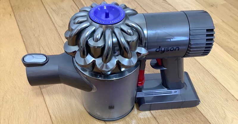
Dyson DC62 Vacuum Cleaner Disassembly

I decided to try to disassemble DC62 Dyson vacuum cleaner.
DC62 is a cordless stick vacuum cleaner, and started being sold in 2013.
I was curious about how the motor structure looked like because It is said that it can rotate at speed of 110,000 rpm. However, I could not find any information what I could be satisfied.
This is an old model, but I decided to disassemble and analyze it. What I am curious to know is how to sense the rotor position, and then what kind of motor drive method is used, and what kind of bearings are used for its bearings.
The cover could be easily removed using a flathead screwdriver doing like the photo shown below, and I could reached the motor circuit board.

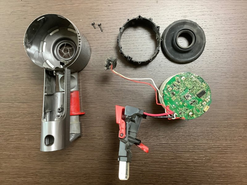
For further disassembly, I needed to remove the solder from the motor coil and circuit board. While melting the solder with a soldering iron, gradually remove the motor coil and circuit board.
After removed the board, it can been seen that one hall sensor is standing for rotor position sensing. There are four transistors for H-bridge, so it can be assumed that the motor drive method is single-phase full-wave.
All four transistors have the same part number on the surface and they are n-ch MOSFETs. The two upper transistors of the H-bridge require charge pumps to boost the gate voltage because the gate voltage must be higher than the source voltage. I think p-ch MOSFETs could be used for the upper switching, but there may be some reason for this.
The PIC microcontroller controls the motor, and the unconnected connector is seemingly for writing programs to the PIC microcontroller.
I can learn more by measuring waveforms with an oscilloscope or current probe, but I will leave it for future occasions.


I assume that the reason why n-ch MOSFETs are used for the upper switching of H-bridge is to mach the characteristics of transistors with the lower MOSFETs.
There are four 1000uF electrolytic capacitors on the power line. Since the rated voltage is 35V, the power voltage for the motor drive should be lower than 35V. Apparently it is 24V.

I assume that the connector with nothing connected is for writing a program to the PIC microcontroller. Apparently, the program will be written in the assembly process.
Although it is simple, I created a circuit schematic. It is assumed that the motor drive and power supply for the control system have different power supplies. The upper n-ch MOSFETs should be driven by boosting the gate voltage with the charge pump. The H-bridge is constructed using four MOSFETs. I assume that the motor drive method is single-phase full-wave drive.
To see the circuit schematic below, just pay JPY ¥200 (around US$1.4).
ここから先は
¥ 200
この記事が気に入ったらサポートをしてみませんか?