ESP32にLCDを接続してみる

概要
ESP32にLCDを接続して描画する実験(2022/12頃の実験)
環境
ESP32 Dev Board
Arduino IDE
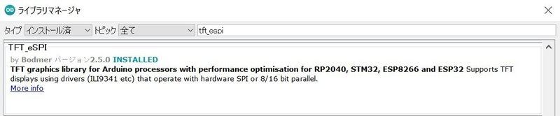
ライブラリマネージャーからインストール
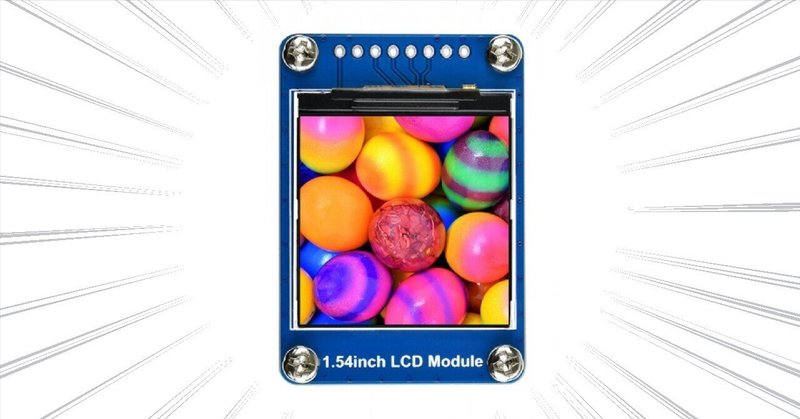
240x240のLCDディスプレイ
ライブラリマネージャーのスクリーンショット
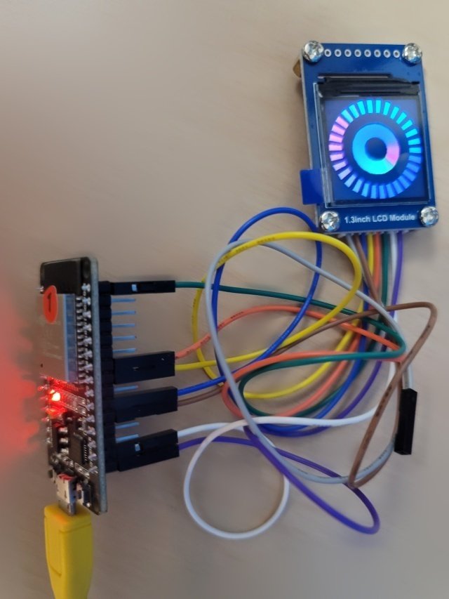
配線
追記(2023/12/9 19:30)
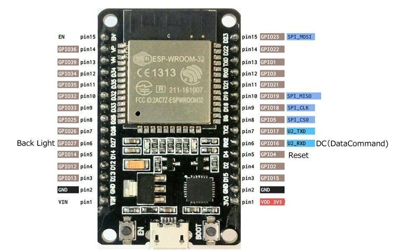
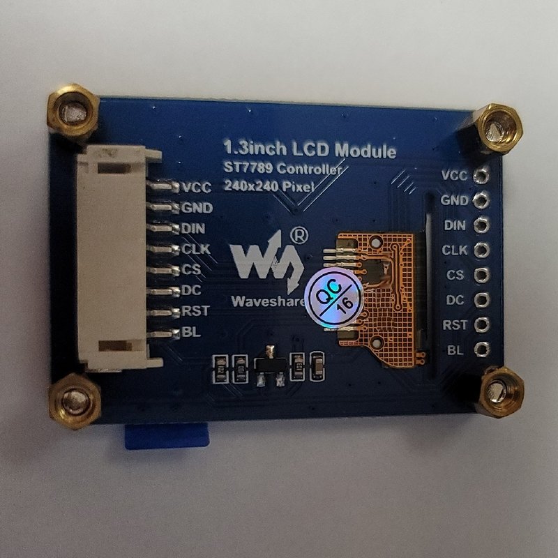
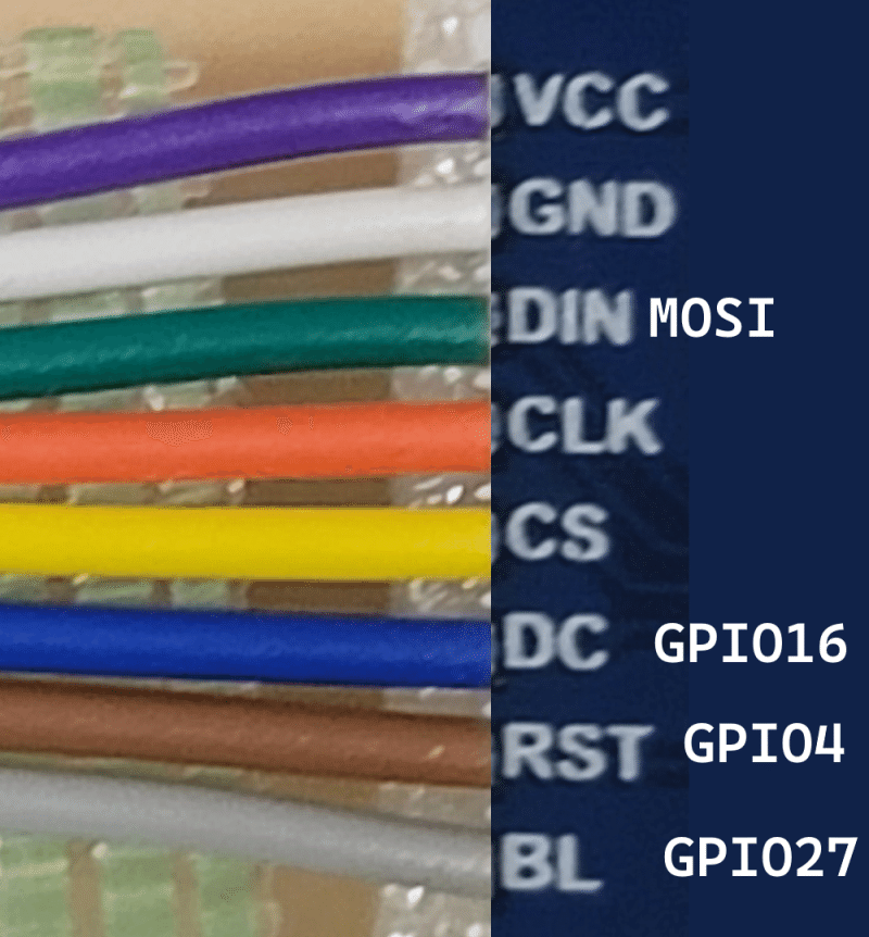
ESP32側 - LCD側で列記する
VDD 3V3 - VCC
GND - GND
SPI_CLK - CLK
SPI_CS0 - CS
SPI_MOSI - DIN
「Master Out Slave In」、ESP32の出力、LCDの入力
SPI_MISOは使用しない
DC(DataCommand)とResetとBackLightは適当なGPIOに接続
GPIOによって、特定の機能が動作しないことがあるので注意
動作確認結果
公式サイトの解説にESP32向けのサンプルがなかったので動作するか不安であったが、無事動いてくれた
3.3V/5Vの両方に対応している、と書かれている
電圧が安定しないと正常に動作しないとも書かれている
TFT_eSPIの設定方法
TFT_eSPIを使うのに、設定が一番の鬼門と思われる
かくいう筆者も、最初に試したとき、設定が間違っていて、
液晶の3分の2しか表示されない状態になり、頭を抱えた
1つしかないと不良品なのか、プログラムが悪いのかの判定が難しい
結局、プログラム(設定)が悪かった
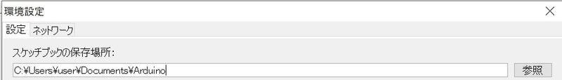
設定ファイルがあるフォルダの確認方法
まず、設定ファイルがどこにあるかを調べる必要がある
環境設定- 設定 - スケッチブックの保存場所:で設定したフォルダのlibrariesフォルダに保存される(はず)
TFT_eSPIを追加すると、TFT_eSPIフォルダが作られる
設定ファイルの編集
libraries/TFT_eSPIフォルダにあるUser_Setup.hを環境に合わせて変更する
以下の項目などを環境に合わせて設定する
使用するドライバ
データの中でのRGBの並び順
液晶のサイズ
SPI関連のピン番号(ESP32 Dev boardという項目を使うと楽)
周波数(特に変更する必要はなかった)
以下に例を示す(コメントアウトを無効化した状態)
#define ST7789_DRIVER

#define TFT_RGB_ORDER TFT_RGB

#define TFT_WIDTH  240
#define TFT_HEIGHT 240

// For ESP32 Dev board (only tested with ILI9341 display)
// The hardware SPI can be mapped to any pins
#define TFT_MISO 19
#define TFT_MOSI 23
#define TFT_SCLK 18
#define TFT_CS   15  // Chip select control pin
#define TFT_DC    2  // Data Command control pin
#define TFT_RST   4  // Reset pin (could connect to RST pin)
#define TFT_RST  -1  // Set TFT_RST to -1 if display RESET is connected to ESP32 board RST

#define SPI_FREQUENCY  27000000
設定ファイルのTips
TFT_eSPIの新しいバージョンを入れると、User_Setup.hが上書きされてしまうことがある問題がある
筆者は、まさにこの状態になり、実験時の設定ファイルが残っていない
対処方法がGitHubに書かれている
TFT_eSPIの上位階層にTFT_eSPI_Setupsフォルダを作り、そのフォルダにUser_Setup.hをコピーする(MySetup.hとする)
User_Setup_Select.hを編集して、MySetup.hを参照するようにする
#include <../TFT_eSPI_Setups/MySetup.h>参考にした情報
If you load a new copy of TFT_eSPI then it will overwrite your setups if they are kept within the TFT_eSPI folder.
One way around this is to create a new folder in your Arduino library folder called "TFT_eSPI_Setups".
You then place your custom setup.h files in there. After an upgrade simply edit the User_Setup_Select.h file to point to your custom setup file e.g.: #include <../TFT_eSPI_Setups/my_custom_setup.h>
プログラム
動作確認時に使用したプログラム
サンプルを少し変更した
虹色の円が描画される
// Demo using arcFill to draw ellipses and a segmented elipse
#include <TFT_eSPI.h> // Hardware-specific library
#include <SPI.h>

TFT_eSPI tft = TFT_eSPI();       // Invoke custom library

#define DEG2RAD 0.0174532925

#define LOOP_DELAY 10 // Loop delay to slow things down

byte inc = 0;
unsigned int col = 0;

byte red = 31; // Red is the top 5 bits of a 16 bit colour value
byte green = 0;// Green is the middle 6 bits
byte blue = 0; // Blue is the bottom 5 bits
byte state = 0;

void setup(void) {
  return;
  tft.begin();

  tft.setRotation(1);

  tft.fillScreen(TFT_WHITE);

  fillArc(120, 120, 0, 60, 60, 60, 60, rainbow(col));

  pinMode(TFT_BL, OUTPUT);

  digitalWrite(TFT_BL, LOW);

  delay(1000);

  digitalWrite(TFT_BL, HIGH);
}


void loop() {
  inc++;
  col += 1;
  if (col > 191) col = 0;
  if (inc > 59) {
    inc = 0;

  }

  delay(LOOP_DELAY);
}

void fillArc(int x, int y, int start_angle, int seg_count, int rx, int ry, int w, unsigned int colour)
{

  byte seg = 6; // Segments are 3 degrees wide = 120 segments for 360 degrees
  byte inc = 6; // Draw segments every 3 degrees, increase to 6 for segmented ring
  float sx = cos((start_angle - 90) * DEG2RAD);
  float sy = sin((start_angle - 90) * DEG2RAD);
  uint16_t x0 = sx * (rx - w) + x;
  uint16_t y0 = sy * (ry - w) + y;
  uint16_t x1 = sx * rx + x;
  uint16_t y1 = sy * ry + y;

  for (int i = start_angle; i < start_angle + seg * seg_count; i += inc) {
    float sx2 = cos((i + seg - 90) * DEG2RAD);
    float sy2 = sin((i + seg - 90) * DEG2RAD);
    int x2 = sx2 * (rx - w) + x;
    int y2 = sy2 * (ry - w) + y;
    int x3 = sx2 * rx + x;
    int y3 = sy2 * ry + y;

    tft.fillTriangle(x0, y0, x1, y1, x2, y2, colour);
    tft.fillTriangle(x1, y1, x2, y2, x3, y3, colour);

    x0 = x2;
    y0 = y2;
    x1 = x3;
    y1 = y3;
  }
}

unsigned int rainbow(byte value)
{
  switch (state) {
    case 0:
      green ++;
      if (green == 64) {
        green = 63;
        state = 1;
      }
      break;
    case 1:
      red--;
      if (red == 255) {
        red = 0;
        state = 2;
      }
      break;
    case 2:
      blue ++;
      if (blue == 32) {
        blue = 31;
        state = 3;
      }
      break;
    case 3:
      green --;
      if (green == 255) {
        green = 0;
        state = 4;
      }
      break;
    case 4:
      red ++;
      if (red == 32) {
        red = 31;
        state = 5;
      }
      break;
    case 5:
      blue --;
      if (blue == 255) {
        blue = 0;
        state = 0;
      }
      break;
  }
  return red << 11 | green << 5 | blue;
}
雑記
ESP32で円形ディスプレイを動かしている動画を見て、秋葉原に購入しにいくも、
土壇場で、隣に陳列されていた四角のディスプレイを購入することにした
やっぱ四角の方がレイアウトしやすいと考えた
動作実績が確認できていなかったので危なかった
土壇場での変更は注意が必要
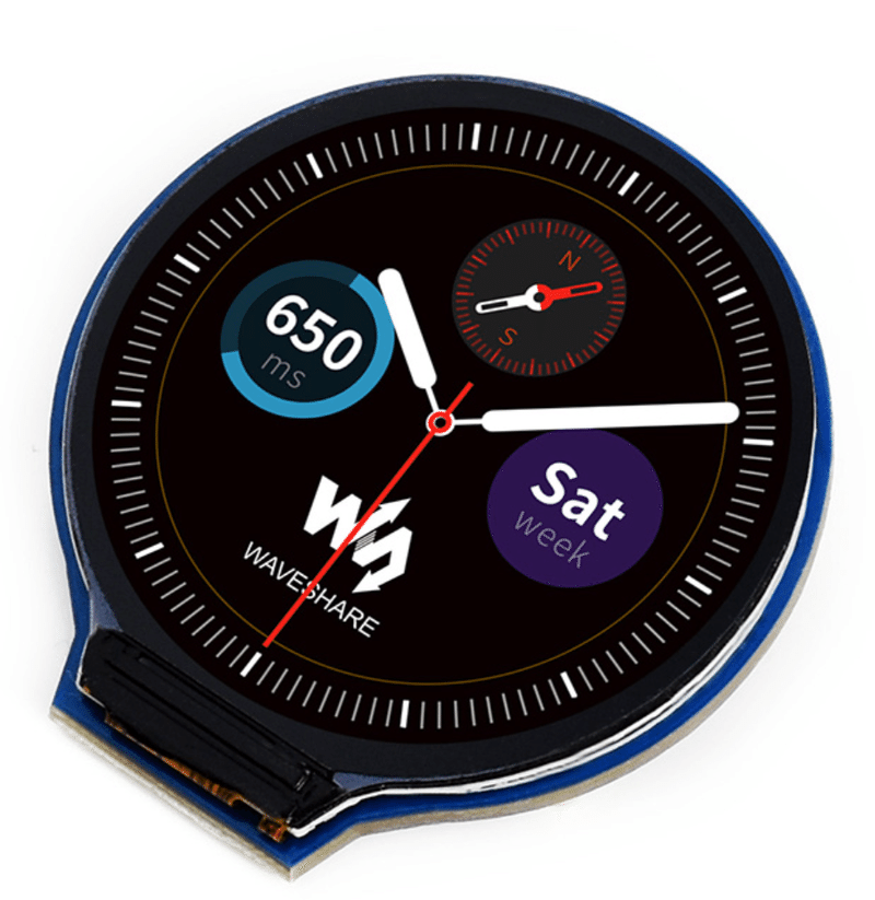
円形は映えるので、円形も欲しい
この記事が気に入ったらサポートをしてみませんか?