
MapleSimでマルチボディ入門

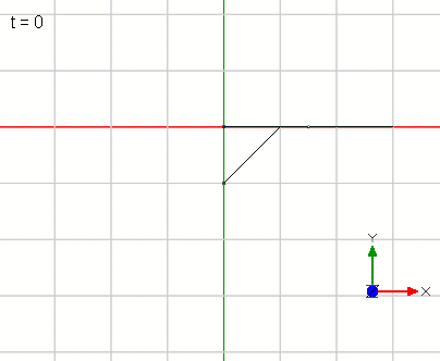
MapleSimのマルチボディライブラリを使って簡単な機構モデルを作ってみます。この記事で作成するモデルの最終形は図1です。片側が回転するリンクをシリンダで上げ下げするモデルです。図2にモデルを動かしたときのアニメーションを表示しています。なお、次の記事で別記事で作成した油圧モデルと連結することを想定して重さや大きさを設定していきます。


リンクモデルの作成
図3に示すようにMapleSimのマルチボディライブラリにある「Fixed Frame」を1つ、「Revolute」を1つ、「Rgid Body」を1つ、「Rigid Body Frame」を2つ配置してつなぎます。
矢印マークの「Rigid Body Frame」は「Rgid Body」とつなぎます。線がかさなっているので「Rigid Body Frame」同士もつながっているように見えますが、つながっていません。
ここで「Rigid Body Frame」についてもう少し補足します。矢印の根本を基準にして矢印の先の位置を指定するブロックです。本例ですと、「Rgid Body」と「Revolute」との距離を指定します。「Rigid Body Frame」を使わずに「Revolute」と「Fixed Frame」がつながっているということは、同じ位置で連結、ようするにかさなっているということになります。
次に各ブロックの設定をしていきましょう。
「Fixed Frame」と「Revolute」はデフォルトの値のままで変更しません。「Rgid Body」は重さmを1000[kg]にします。それ以外はデフォルトの値のままにします。
左側の「Rigid Body Frame」は図4に示すようにパラメータの「r」のところを[-1.5, 0, 0]に設定します。それ以外はデフォルトの値のままにします。この設定によって「Rgid Body」からx方向に-1.5[m]の位置に接続点を作ることができました。
右側の「Rigid Body Frame」の「r」のところを[1.5, 0, 0]に設定します。それ以外はデフォルトの値のままにします。この設定によって「Rgid Body」からx方向に1.5[m]の位置に接続点を作ることができました。こちらは現時点ではただ描画のためだけのものになります。
これらの設定によって3[m]のリンクで、その中心位置に1000[kg]の集中重心の物体をを作ることができました。
そしてリンクの左側が「Revolute」を介して「Fixed Frame」(固定点)に連結されていますから、リンクの回転モデルを作ることができました。

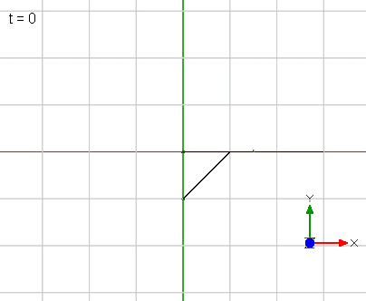
シミュレーションを実行すると図5の運動を見ることができます。
3[m]のリンクが重力によって振り子運動をしていることがわかります。

シリンダを追加
シリンダを図2に示したように「Rgid Body」から左に-0.5[m]の位置(「Revolute」との接点から右に1[m]の位置)接続するために、接続点を設定する「Rigid Body Frame」を新たに設置して「Rgid Body」とつなげます(図6)。新たに追加した「Rigid Body Frame」の「r」のところを[-0.5, 0, 0]に設定します。それ以外はデフォルトの値のままにします。この設定によって「Rgid Body」からx方向に-0.5[m]の位置に接続点を作ることができました。
次にシリンダの機構部分を追加します。
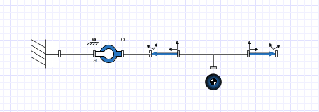
図7に示すように、新たに「Fixed Frame」1つと「Revolute」2つ、「Prismatic」を配置してつなげます。
「Prismatic」は1つの並進方向可動させるジョイントです。これによってシリンダの伸び縮みを表現します。
次に各ブロックの設定をしていきましょう。
「Prismatic」の設定はデフォルトのままです。
「Fixed Frame」のパラメータの「r」のところを[0, -1, 0]に設定します。それ以外はデフォルトの値のままにします。この設定によって「Fixed Frame」は[0, -1, 0]、要するにy方向に-1[m]の位置に設置したことになります。
追加した2つの「Revolute」は設定を必要とします。
「Prismatic」の左側に設置した「Revolute」の設定は図8に示すようにθ0の値を45[deg]に設定します。最初単位が[rad]になっているので単位も変更します。それ以外はデフォルトの値のままにします。
「Prismatic」の右側に設置した「Revolute」の設定θ0の値を-45[deg]に設定します。それ以外はデフォルトの値のままにします。

シミュレーションを実行してみます。実行結果は図9にようになります。
一見すると何も図5と何もかわっていないように見えます。シリンダ部分の描画がないからです。

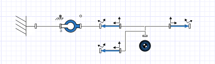
「Rigid Body Frame」を使ってダミーの絵をつけます。
図10に示すように2つの「Rigid Body Frame」を「Prismatic」の上に配置します。
左側の「Rigid Body Frame」は「Prismatic」の左側の「Revolute」とつなぎます。右側の「Rigid Body Frame」は「Prismatic」の右側の端子とつなぎます。「Prismatic」と接続したのはロッド部分が「Prismatic」の拘束によってシリンダボディ部分と並行して動いてほしいからです。
左側の「Rigid Body Frame」の設定はrを[1, 0, 0]にします。これはシリンダの最も縮まったときの長さをイメージしています。
右側の「Rigid Body Frame」の設定はrを[-0.8, 0, 0]にします。これはシリンダの可動部分であるロッド部分をイメージしています。-0.8としているのは接続した「Revolute」を基準にして「Prismatic」側へ設置するためにマイナスとしています。
それではシミュレーションを実行してみましょう(図11)。
「Prismatic」の拘束によってシリンダが動いていることがわかりますね。
シリンダの反力がないので突き抜けていますので、次にシリンダ反力を追加していきましょう。
油圧シリンダの追加
油圧モデルの詳細は以下の記事を参照してもらうとして、本記事では簡単に説明します。
MapleSimで超簡単な油圧モデルを作ってみた#4(方向切り替えバルブでシリンダを動かしてみる)|齋藤芳明 (note.com)
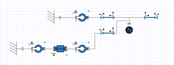
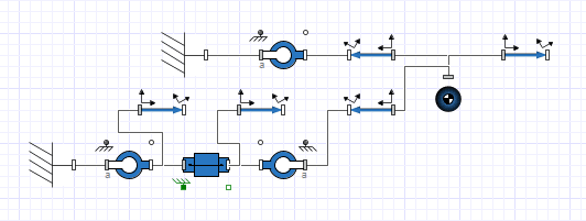
図12に油圧モデルを追加したモデルを表示しています。
油圧シリンダ、ポンプ、タンク、リリーフバルブとチャンバーです。
ドラム缶のマークは作動油の設定になります。
ポンプ圧を見たいので油圧センサと「Probe」を設置します。
油圧シリンダは「Prismatic」の両端とつなぎます。
油圧ブロックの設定をしていきます。
ドラム缶のマークの作動油の設定はデフォルトの値のままにします。
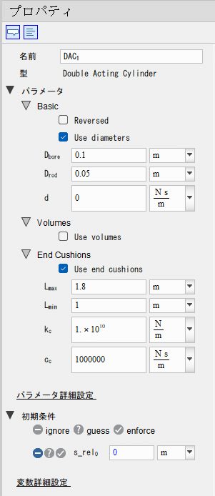
油圧シリンダの設定は図13のようにします。今回一番大事な設定はLmaxとLminです。シリンダが最も伸びたときの長さと縮んだときの長さです。
本モデルではLmaxを1.8[m]、Lminを1[m]に設定しています。
油圧ポンプは流量Qを50[L/min]に設定します。単位の変更も忘れずにしましょう。
チャンバーの容量Vを0.0001[m^3]にします。
リリーフバルブの設定はPcloseを38[MPa]、Popenを40[MPa]に設定します。
油圧センサは圧力の単位を[MPa]にしておきます。
シミュレーションを実行すると図14のようになります。
油圧も見てみよう
ポンプ圧を見ると図15のようになります。
3.8[s]くらいまでジャミジャミして100[MPa]を超えるピーク圧の後に40[MPa]弱で安定しています。3.8[s]くらいで油圧シリンダのストロークエンドに到達して、以後はリリーフしていることがわかります。
おおよそ動きはわかりますが、3.8[s]くらいまでジャミジャミしているところが気になります。これは圧が立ってリンクが動くのですが、リンクが動くとポンプからの流量よりリンクの動き、すなわちシリンダの動きが大きくなって圧が低下して、さらに圧が低下したためにリンクの動きが遅くなって、圧が上がるというのを短い時間で繰り返しているのです。現実にはこのようなことは起こりませんので、そのことを理解したうえでこのまま使うのでもよいですが、今回は回避方法の一例を紹介します。

油圧シリンダの設定であるダンパ抵抗dを1000000[Ns/m]にします。ダンパ抵抗によって急激なシリンダの速度変化を抑止できるので、図15のようにポンプ圧の振動を抑制することができます。
この対応は完璧な唯一無二の方法ではありません。よく考えずにこういった処置ばかりすると適切なモデル化になりませんので、十分に考えて対応するようにしましょう。

【English】
We will create a simple mechanism model using MapleSim's multibody library. The final form of the model we will create in this article is shown in Figure 1. The model is a cylinder that raises and lowers a link that rotates on one side. Figure 2 shows an animation of the model in motion. In the next article, we will set the weight and size of the model, assuming that it will be connected to the hydraulic model created in a separate article.
Creating a Linked Model
As shown in Figure 3, place and connect the "Fixed Frame," "Revolute," "Rigid Body," and two "Rigid Body Frames" from the MapleSim multi-body library. The "Rigid Body Frame" marked with an arrow is connected to the "Rigid Body. The overlapping lines make it look like the Rigid Body Frames are connected to each other, but they are not. Here are a few more details about the "Rigid Body Frame. The "Rigid Body Frame" is a block that specifies the position of the end of the arrow based on the root of the arrow. In this example, it specifies the distance between the "Rigid Body" and the "Revolute. If "Revolute" and "Fixed Frame" are connected without "Rigid Body Frame," it means that they are connected at the same position, or in other words, they are overlapped.
Next, let's set up each block. Fixed Frame" and "Revolute" are left unchanged at their default values. For "Rgid Body," set the weight m to 1000[kg]. Otherwise, leave the default values as they are. For "Rigid Body Frame" on the left side, set the parameter "r" to [-1.5, 0, 0] as shown in Figure 4. Leave the other parameters at their default values. With this setting, we have created a connection point at -1.5[m] in the x direction from the "Rigid Body. Set "r" in "Rigid Body Frame" on the right side to [1.5, 0, 0]. Otherwise, leave the default values. With this setting, we have created a connection point at 1.5[m] in the x-direction from the "Rigid Body". This is just for drawing purposes at this time. With these settings, we have created an object with a concentrated center of gravity of 1000[kg] at its center position with a link of 3[m]. And since the left side of the link is connected to the "Fixed Frame" (fixed point) via "Revolute," we were able to create a rotational model of the link.
Running the simulation we can see the motion in Figure 5, where we can see that the 3[m] link is in pendulum motion due to gravity.
Adding Cylinder Model
To connect the cylinder at -0.5[m] to the left from the "Rigid Body" (1[m] to the right from the contact point with the "Revolute") as shown in Figure 2, set up a new "Rigid Body Frame" that sets the connection point and connect it to the "Rigid Body" (Figure 6). Set the "r" of the newly added "Rigid Body Frame" to [-0.5, 0, 0]. Otherwise, leave the default values. With this setting, we have created a connection point at -0.5[m] in the x-direction from the "Rigid Body.
Next, add the mechanism part of the cylinder. As shown in Figure 7, one new "Fixed Frame," two new "Revolute," and a new "Prismatic" are placed and connected. The "Prismatic" is a single translational joint. This joint is used to express the expansion and contraction of the cylinder.
Next, let's set up each block. Leave the "Prismatic" setting at the default. In the "Fixed Frame" parameter, set "r" to [0, -1, 0]. Otherwise, leave the default values. This will place the "Fixed Frame" at [0, -1, 0], in other words, at -1[m] in the y direction. The two additional "Revolute" settings are required. The "Revolute" on the left side of the "Prismatic" needs to be set to a value of 45[deg] for θ0, as shown in Figure 8. Since the unit is initially set to [rad], change the unit as well. Otherwise, leave the default values as they are. Set the value of θ0 to -45[deg] for the "Revolute" setting on the right side of "Prismatic. Otherwise, leave the default value.
Run the simulation. The result is shown in Figure 9. At first glance, it looks as if nothing has changed from Figure 5. This is because the cylinder portion is not drawn.
Use the "Rigid Body Frame" to add a dummy picture. Place the two "Rigid Body Frames" on top of the "Prismatic" as shown in Figure 10. The left Rigid Body Frame is connected to the left Revolute on the Prismatic. The right "Rigid Body Frame" is connected to the right terminal on the "Prismatic". The reason for connecting it to the "Prismatic" is that the rod part should move in parallel with the cylinder body part due to the constraints of the "Prismatic". For the "Rigid Body Frame" setting on the left side, set r to [1, 0, 0]. This is the length of the cylinder when it is at its most compressed. For the "Rigid Body Frame" setting on the right, set r to [-0.8, 0, 0]. This is to imagine the rod portion, which is the movable portion of the cylinder. The -0.8 setting is a minus value to place it on the "Prismatic" side with respect to the connected "Revolute".
Now let's run the simulation (Figure 11). You can see that the cylinder is moving due to the "Prismatic" constraint. Since there is no cylinder reaction force, it is pushing through, so let's add a cylinder reaction force next.
Additional Hydraulic Cylinder
The details of the hydraulic model are explained briefly in this article, with references to the following articles.
MapleSimで超簡単な油圧モデルを作ってみた#4(方向切り替えバルブでシリンダを動かしてみる)|齋藤芳明 (note.com)
Figure 12 displays the model with the hydraulic model added. It is a hydraulic cylinder, pump, tank, relief valve and chamber. The drum symbol is for the hydraulic oil setup. We want to see the pump pressure, so we install a hydraulic pressure sensor and "Probe". The hydraulic cylinder is connected to both ends of the "Prismatic".
The hydraulic block will be set up. Leave the hydraulic oil setting for the drum symbol at the default value. The settings for the hydraulic cylinder should be as shown in Figure 13. The most important settings this time are Lmax and Lmin. These are the length of the cylinder when it is most extended and the length of the cylinder when it is shortened. In this model, Lmax is set to 1.8[m] and Lmin to 1[m].
For the hydraulic pump, set the flow rate Q to 50 [L/min]. Do not forget to change the units. Set the chamber volume V to 0.0001[m^3]. For the relief valve, set Pclose to 38[MPa] and Popen to 40[MPa]. For the oil pressure sensor, set the unit of pressure to [MPa]. When the simulation is run, the result is as shown in Figure 14.
Let's also look at Hydraulics.
The pump pressure is shown in Figure 15, which shows that the pressure is stable at a little less than 40 MPa after a peak pressure of over 100 MPa, which is reached at about 3.8[s], and then relieved. Although we can see the approximate movement, we are concerned about the jerky movement up to about 3.8[s]. This is because the linkage moves as the pressure builds up, but when the linkage moves, the movement of the linkage, or cylinder, becomes greater than the flow rate from the pump, causing the pressure to drop, and then the linkage slows down as the pressure drops, causing the pressure to rise, which is repeated in a short period of time. In reality, this does not happen, so it is fine to understand this and use the system as it is, but this time we will introduce an example of how to avoid it.
The damper resistance d, which is the setting of the hydraulic cylinder, is set to 1000000[Ns/m]. The damper resistance can deter rapid cylinder speed changes, thus suppressing pump pressure oscillations as shown in Figure 15. This response is not a perfect one-and-only method. If you take all of these measures without careful consideration, you will not be able to model properly, so be sure to give the measures sufficient thought.
【Sample Model】
Created by MapleSim 2023
この記事が気に入ったらサポートをしてみませんか?