ルアー周りの流れ(potential flow偏)

ルアー周りの流れをopenFoamをつかって解きます.
ルアーに関する形状は色々でてて,様々な特性が言及されていると思いますが,専門家が流れを解いて考察している人はどれだけいるでしょうか
自分はここに目を付けました.
最終的なゴールは,界面,動的なルアーと流体の動きを同時に解くことですすが,まずその手始めとして,ポテンシャル流の計算をしました.
ポテンシャル流を解くメリットとしては,1.おおよその流れがわかる,2.物体(ルアー)が存在することで物体遠方にどこまで影響を及ぼすかわかり必要な計算領域がわかる.ポテンシャル流は非粘性流体の特性をつかむことができ,計算が用意である.
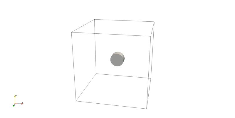
stlで生成した物体のポテンシャル流を解くひな形(openFoam)を,まず円柱で行う.
まず適当に円柱をFreeCADでつくります.
*/constasnt/triSurface/cylinder.stl
上記のディレクトリに作った円柱のstlファイルcylinder.stlを入れます.
フォルダがない場合は作ってください.
*/system/blockMeshDictに
/*--------------------------------*- C++ -*----------------------------------*\
========= |
\\ / F ield | OpenFOAM: The Open Source CFD Toolbox
\\ / O peration | Website: https://openfoam.org
\\ / A nd | Version: 10
\\/ M anipulation |
\*---------------------------------------------------------------------------*/
FoamFile
{
version 2.0;
format ascii;
class dictionary;
object blockMeshDict;
}
// 全体のサイズ
convertToMeters 50;
// 頂点の座標を定義
vertices
(
(-1 -1 -1)
( 1 -1 -1)
( 1 1 -1)
(-1 1 -1)
(-1 -1 1)
( 1 -1 1)
( 1 1 1)
(-1 1 1)
);
// 頂点を使用してブロックを定義
blocks
(
hex (0 1 2 3 4 5 6 7) (50 50 50) simpleGrading (1 1 1)
);
// 境界条件を定義
boundary
(
inlet
{
type patch;
faces
(
(0 4 7 3)
);
}
outlet
{
type patch;
faces
(
(1 2 6 5)
);
}
top
{
type patch;
faces
(
(2 3 7 6)
);
}
bottom
{
type patch;
faces
(
(0 1 5 4)
);
}
right
{
type patch;
faces
(
(4 5 6 7)
);
}
left
{
type patch;
faces
(
(0 1 2 3)
);
}
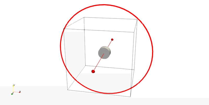
);を書きます.これは計算領域を決めます.大体上記のように直方体に作ります.次は,FreeCADで作ったstlファイルに対し,openFoamのメッシュ作成に必要な表面情報を作ります.
ターミナルコマンド
root>>blockMeshで生成完了
root>>paraFoamで確認.(突然消えてしまうことがありますが,これはU,Pが格子とU,Pの格子点数があっていないため.U,Pのチェックを外してapplyを押せば可視化できるはず.計算領域が意図したものかどうかチェックしてほしい.)
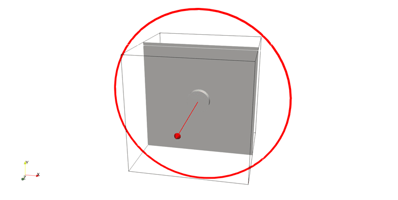
次に,FreeCADで作ったstlファイルをもとに物体の情報を作っていきます.
下記のファイルをいじります.ない場合は作ってくれればよい.
*/system/surfaceFeaturesDict
/*--------------------------------*- C++ -*----------------------------------*\
  =========                 |
  \\      /  F ield         | OpenFOAM: The Open Source CFD Toolbox
   \\    /   O peration     | Website:  https://openfoam.org
    \\  /    A nd           | Version:  10
     \\/     M anipulation  |
\*---------------------------------------------------------------------------*/
FoamFile
{
    version     2.0;
    format      ascii;
    class       dictionary;
    object      surfaceFeaturesDict;
}
// * * * * * * * * * * * * * * * * * * * * * * * * * * * * * * * * * * * * * //

surfaces ("cylinder.stl");

// Identify a feature when angle between faces < includedAngle
includedAngle   150;

// ************************************************************************* //
*/system/meshQualityDict
/*--------------------------------*- C++ -*----------------------------------*\
  =========                 |
  \\      /  F ield         | OpenFOAM: The Open Source CFD Toolbox
   \\    /   O peration     | Website:  https://openfoam.org
    \\  /    A nd           | Version:  10
     \\/     M anipulation  |
\*---------------------------------------------------------------------------*/
FoamFile
{
    format      ascii;
    class       dictionary;
    object      meshQualityDict;
}

// * * * * * * * * * * * * * * * * * * * * * * * * * * * * * * * * * * * * * //

// Include defaults parameters from master dictionary #includeEtc  "caseDicts/mesh/generation/meshQualityDict"


// ************************************************************************* //
とし,下記のコマンドを打つ.
root>>surfaceFeaturesこれで,物体周りの情報が作れたはず.(エラーが出ていなければ)
次に,blockMeshで作った計算領域に物体情報を入れ込みます.下記のファイルをいじります.(ない場合は作って)
*/system/snappyHexMeshDict
/*--------------------------------*- C++ -*----------------------------------*\
  =========                 |
  \\      /  F ield         | OpenFOAM: The Open Source CFD Toolbox
   \\    /   O peration     | Website:  https://openfoam.org
    \\  /    A nd           | Version:  10
     \\/     M anipulation  |
\*---------------------------------------------------------------------------*/
FoamFile
{
    version     2.0;
    format      ascii;
    class       dictionary;
    object      snappyHexMeshDict;
}
// * * * * * * * * * * * * * * * * * * * * * * * * * * * * * * * * * * * * * //

castellatedMesh true;
snap            true;
addLayers       false;

geometry
{
    cylinder.stl
    {
        type triSurfaceMesh;
        name cylinder;
    };
};

castellatedMeshControls
{
    maxLocalCells 1000000;
    maxGlobalCells 2000000;
    minRefinementCells 0;
    nCellsBetweenLevels 3;
    resolveFeatureAngle 30;  // 例として30度を使用
    features
    (
        { file "cylinder.eMesh"; level 2; }
    );

    refinementSurfaces
    {
        cylinder
        {
            level (3 4);
        }
    }

    refinementRegions
    {
        // This section is optional and can be customized or omitted
    }

    locationInMesh (30 30 20); // Adjust this to be inside the mesh
    allowFreeStandingZoneFaces true;
}

snapControls
{
    nSmoothPatch 3;
    tolerance 2.0;
    nSolveIter 1;
    nRelaxIter 1;
}

addLayersControls
{
    // This section is not used since addLayers is set to false
}

meshQualityControls
{
    #include  "meshQualityDict"

    relaxed
    {
        maxNonOrtho 10;
    }
}

mergeTolerance 1e-3;

// ************************************************************************* //
ここで,物体表面近傍のメッシュ等の作成ができる.ポテンシャル流では関係ないので,こだわなくてよい.境界層を正しく解く計算のときはちゃんと設定します.これは書き終わったら,コマンドに以下の指令を出せばポテンシャル流が計算できます.
root>>optentialFoam計算結果はparaFoamというコマンドを打てばできますが,wslで可視化すると,paraviewがバグる.そこでwindowsでparaviewを起動しそこで可視化することを考える.
root>>foamToVTKのコマンドを打つことでVTKファイルが作られてwindowsのparaviewで可視化できます.
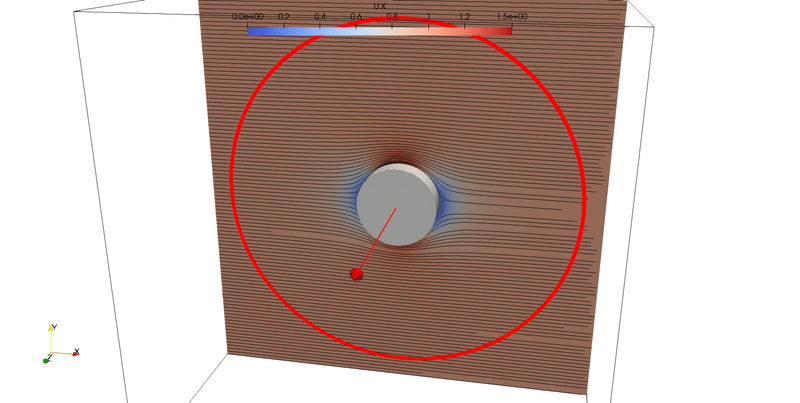
こんな感じ.これでひな形完成.
stlファイルを作ったルアーにしてみます.
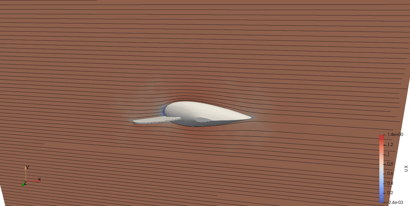
こんな感じ.
次回,粘性流体にチャレンジ.
この記事が気に入ったらサポートをしてみませんか?