自作トラッカーを作ろう【SlimeVR】Part3ソフトウエア編

始めに
前回に続きソフトウエア編になります。ファームウェア?プログラミングするのって思うかもしれませんがコピペするだけなので簡単です。
必要なアプリケーションをインストールするところから始めます。
今回はESP32mini、M5stampC3のFWに関してのみ書きます。それ以外のモジュールに関しては公式Docsを参照するかSlimeVR公式Discordにてお問い合わせください。
PART1
PART2
SlimeVR用PCB 専用ケースデータも配布しています
必要なソフトウエア
Visual Studio Code
ESP32、ESP8266等にファームウェアを書き込む為のソフト
そのままインストールしてください。
※起動後PratformIO IDEをインストール
Gitクライアント
GitHubからデータをクローンするのに使う。
英語で書かれていますがそのままインストールを進めてください。
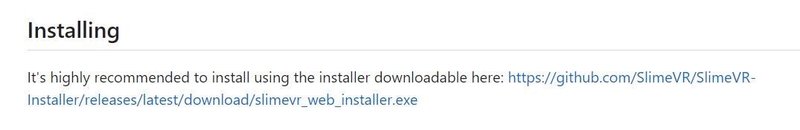
SlimeVRserver
SlimeVRトラッカーを制御するアプリ。Windows版やAndroid版もある。
キャリブレーションや各トラッカーのWiFi設定各部位への割り当てを行う。
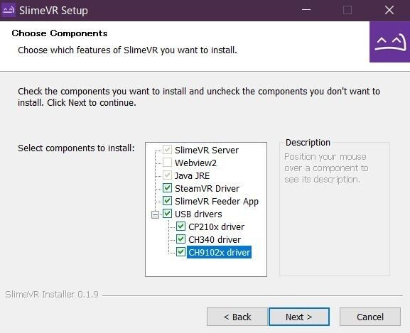
※USBドライバーについて
先にSlimeVRServerをインストールしておくとESP32やESP8266のUSBシリアルドライバが入ります。VScodeでFWをアップロードする際にUSBのドライバが必要になります。
2024/1/1追記
先日、市販のSlimeVRトラッカーを購入された方から相談があり、
USBドライバーを全てインストールすると、競合してしまいWiFi設定を書き込め無くなる症状を確認いたしました。お使いのモジュールのUSB通信モジュールを確認の上USBドライバーを選択してください。
ファームウェアの書き込み
VScodeを起動します。
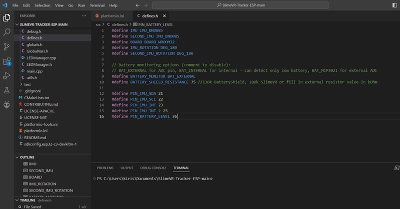
編集するのはplatformIO.iniとsrc/defines.hだけです。
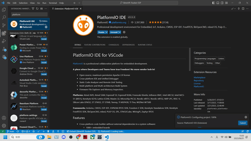
①左タブのEXTENSIONSでPratformIO IDEをインストールしてください。
インストール後Enableになっていることも確認。
※こちらをインストールしていないとESP32、ESP8266にFWが書き込めません
2024/1/12
FWがv17になっていたので更新しました。
v16以降BNO080/BNO085/Bmi160等AD0からGNDへの配線が増えたりSlimeVR公式販売のBNO085に関してはSD0のブリッジが必要になっております。詳しくはハードウェア編に記載しています。
こちらで動作確認が取れたので
M5stampC3用、esp32mini用のFWを公開いたします。
本記事で紹介した配線、モジュールにを使用して作成する場合はこちらをダウンロードしセンサーの種類、角度を設定し書き込むだけです。
使い方
GoogleDriveからダウンロード後解凍し、VScodeのFile→OpenFolderからSlimeVR-Tracker-ESPを開いてください。
あとは必要に応じてセンサーの種類、角度等変更してモジュールに書き込んでください。⑤まで省略。
ESP32mini slimeVR v17
https://drive.google.com/file/d/1GD7O1_mKeTKEa8BjkJ4nO4v-bmDq4QER/view?usp=sharing
M5stampC3 slimeVR v17
https://drive.google.com/file/d/1qOMLSnCYBXOtkhppALwO8qSIwXhCbB1C/view?usp=sharing
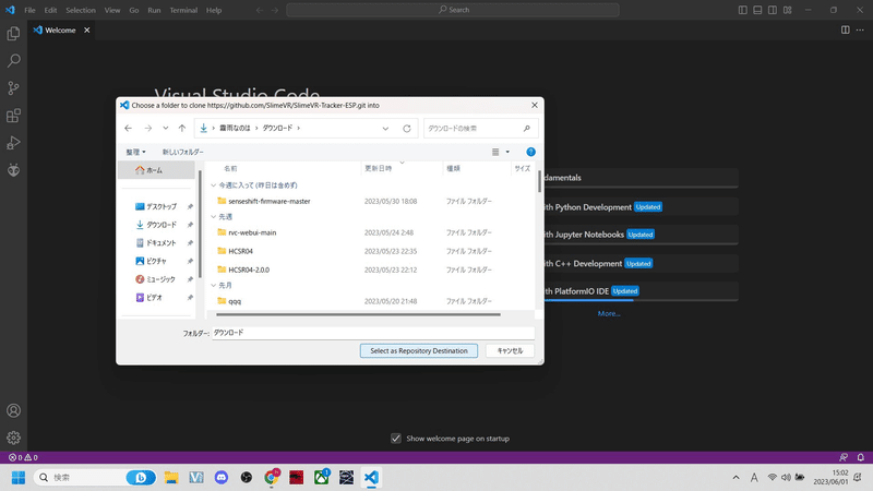
②画面中央のclone git repositryをクリック

③上部に出てくるアドレスバー以下を入力し保存先を指定する
クローン後に開くか聞かれるのでOPENをクリック
https://github.com/SlimeVR/SlimeVR-Tracker-ESP.git


④FWがロードされるのでplatformio.iniとsrc/defines.hの2つを開き全てのコードをバックスペースキーで削除してください。

2024/1/12追記
コピペしてお使いください。
ESP32mini 最新版
Platfomio.ini
; PlatformIO Project Configuration File
;
;   Build options: build flags, source filter
;   Upload options: custom upload port, speed and extra flags
;   Library options: dependencies, extra library storages
;   Advanced options: extra scripting
;

; ================================================
; See docs for configuration options and examples:
; https://docs.slimevr.dev/firmware/configuring-project.html#1-configuring-platformioini
; ================================================

[env]
lib_deps=
  https://github.com/SlimeVR/CmdParser.git
  https://github.com/SlimeVR/base64_arduino.git
monitor_speed = 115200
monitor_echo = yes
monitor_filters = colorize
;monitor_rts = 0
;monitor_dtr = 0
framework = arduino
build_flags =
  !python scripts/get_git_commit.py
;If you want to set hardcoded WiFi SSID and password, uncomment and edit the lines below
;To uncomment, only remove ";" and leave the two spaces in front of the tags
; '" - quotes are necessary!
;  -DWIFI_CREDS_SSID='"SSID"'
;  -DWIFI_CREDS_PASSWD='"PASSWORD"'

;If you want to set a static IP address, uncomment and edit the lines below
;  -DWIFI_USE_STATICIP
;  -DWIFI_STATIC_IP=192,168,XXX,XXX
;  -DWIFI_STATIC_GATEWAY=192,168,XXX,XXX
;  -DWIFI_STATIC_SUBNET=255,255,255,0

; Uncomment below if your board are using 40MHz crystal instead of 26MHz for ESP8266
;  -DF_CRYSTAL=40000000

; Enable -O2 GCC optimization
  -O2
  -std=gnu++17

build_unflags = -Os -std=gnu++11

; If you want to enable OTA Updates, uncomment and set OTA password here and in credentials.h
; You can set upload_port to device's ip after it's set up for the first time
; Use the same password in SlimeVR Server to let it OTA Update the device
;upload_protocol = espota
;upload_port = 192.168.1.49
;upload_flags =
;  --auth=SlimeVR-OTA

; Settings for different boards

;[env:esp12e]
;platform = espressif8266 @ 4.2.0
;board = esp12e
; Comment out this line below if you have any trouble uploading the firmware
; and if it has a CP2102 on it (a square chip next to the usb port): change to 3000000 (3 million) for even faster upload speed
;upload_speed = 921600

; Uncomment below if you want to build for ESP-01
;[env:esp01_1m]
;platform = espressif8266 @ 4.2.0
;board = esp01_1m
;board_build.arduino.ldscript = "eagle.flash.1m64.ld"

; Uncomment below if you want to build for ESP8285 (ESP8266 with embedded Flash)
;[env:esp8285]
;platform = espressif8266 @ 4.2.0
;board = esp8285
;board_build.arduino.ldscript = "eagle.flash.1m64.ld"
;board_build.flash_mode = dout

; Uncomment below if you want to build for esp32
; Check your board name at https://docs.platformio.org/en/latest/platforms/espressif32.html#boards
;[env:esp32]
;platform = espressif32 @ 6.1.0
;board = esp32dev
; Comment out this line below if you have any trouble uploading the firmware - and if it has a CP2102 on it (a square chip next to the usb port): change to 3000000 (3 million) for even faster upload speed
;upload_speed = 921600

; If you want to use a ESP32C3, you can use this (experimental)
; Check your board name at https://docs.platformio.org/en/latest/platforms/espressif32.html#boards
; There are 2 main Boardtypes:
; 1. Boards that use a USB 2 Serial Chipset ( esp32-c3-devkitm-1, ttgo-t-oi-plus )
; 2. Boards that relay on the USB interface of the ESP32C3 ( lolin_c3_mini , dfrobot_beetle_esp32c3)
;    On this board there are 2 type some of them need to have set the build flag (menuconfig)
;    -DARDUINO_USB_MODE=1
;    -DARDUINO_USB_CDC_ON_BOOT=1

;[env:esp32c3]
;platform = espressif32 @ 6.1.0
;build_flags =
;  ${env.build_flags}
;  -DESP32C3
;board = lolin_c3_mini


[env:mhetesp32minikit]
platform = espressif32@ 6.1.0
board = mhetesp32minikit
defines.h
/*
    SlimeVR Code is placed under the MIT license
    Copyright (c) 2021 Eiren Rain

    Permission is hereby granted, free of charge, to any person obtaining a copy
    of this software and associated documentation files (the "Software"), to deal
    in the Software without restriction, including without limitation the rights
    to use, copy, modify, merge, publish, distribute, sublicense, and/or sell
    copies of the Software, and to permit persons to whom the Software is
    furnished to do so, subject to the following conditions:

    The above copyright notice and this permission notice shall be included in
    all copies or substantial portions of the Software.

    THE SOFTWARE IS PROVIDED "AS IS", WITHOUT WARRANTY OF ANY KIND, EXPRESS OR
    IMPLIED, INCLUDING BUT NOT LIMITED TO THE WARRANTIES OF MERCHANTABILITY,
    FITNESS FOR A PARTICULAR PURPOSE AND NONINFRINGEMENT. IN NO EVENT SHALL THE
    AUTHORS OR COPYRIGHT HOLDERS BE LIABLE FOR ANY CLAIM, DAMAGES OR OTHER
    LIABILITY, WHETHER IN AN ACTION OF CONTRACT, TORT OR OTHERWISE, ARISING FROM,
    OUT OF OR IN CONNECTION WITH THE SOFTWARE OR THE USE OR OTHER DEALINGS IN
    THE SOFTWARE.
*/
// ================================================
// See docs for configuration options and examples:
// https://docs.slimevr.dev/firmware/configuring-project.html#2-configuring-definesh
// ================================================

// Set parameters of IMU and board used
#define IMU IMU_MPU6050
#define SECOND_IMU IMU
#define BOARD BOARD_WROOM32
#define IMU_ROTATION DEG_180
#define SECOND_IMU_ROTATION DEG_180

#define PRIMARY_IMU_OPTIONAL false
#define SECONDARY_IMU_OPTIONAL true

#define MAX_IMU_COUNT 1

// Axis mapping example
/*
 #include "sensors/axisremap.h"
#define BMI160_QMC_REMAP AXIS_REMAP_BUILD(AXIS_REMAP_USE_Y, AXIS_REMAP_USE_XN, AXIS_REMAP_USE_Z, \
                                       AXIS_REMAP_USE_YN, AXIS_REMAP_USE_X, AXIS_REMAP_USE_Z)

IMU_DESC_ENTRY(IMU_BMP160, PRIMARY_IMU_ADDRESS_ONE, IMU_ROTATION, PIN_IMU_SCL, PIN_IMU_SDA, BMI160_QMC_REMAP) \
*/

 #ifndef IMU_DESC_LIST
#define IMU_DESC_LIST \
        IMU_DESC_ENTRY(IMU,        PRIMARY_IMU_ADDRESS_ONE,   IMU_ROTATION,        PIN_IMU_SCL, PIN_IMU_SDA, PRIMARY_IMU_OPTIONAL,   PIN_IMU_INT) \

#endif

// Battery monitoring options (comment to disable):
//   BAT_EXTERNAL for ADC pin,
//   BAT_INTERNAL for internal - can detect only low battery,
//   BAT_MCP3021 for external ADC connected over I2C
#define BATTERY_MONITOR BAT_EXTERNAL
#define BATTERY_SHIELD_RESISTANCE 70
// BAT_EXTERNAL definition override
// D1 Mini boards with ESP8266 have internal resistors. For these boards you only have to adjust BATTERY_SHIELD_RESISTANCE.
// For other boards you can now adjust the other resistor values.
// The diagram looks like this:
//   (Battery)--- [BATTERY_SHIELD_RESISTANCE] ---(INPUT_BOARD)---  [BATTERY_SHIELD_R2] ---(ESP32_INPUT)--- [BATTERY_SHIELD_R1] --- (GND)
// #define BATTERY_SHIELD_RESISTANCE 180 //130k BatteryShield, 180k SlimeVR or fill in external resistor value in kOhm
// #define BATTERY_SHIELD_R1 100 // Board voltage divider resistor Ain to GND in kOhm
// #define BATTERY_SHIELD_R2 220 // Board voltage divider resistor Ain to INPUT_BOARD in kOhm

// LED configuration:
// Configuration Priority 1 = Highest:
// 1. LED_PIN
// 2. LED_BUILTIN
//
//   LED_PIN
//     - Number or Symbol (D1,..) of the Output
//     - To turn off the LED, set LED_PIN to LED_OFF
//   LED_INVERTED
//     - false for output 3.3V on high
//     - true for pull down to GND on high

// Board-specific configurations
#if BOARD == BOARD_SLIMEVR
  #define PIN_IMU_SDA 14
  #define PIN_IMU_SCL 12
  #define PIN_IMU_INT 16
  #define PIN_IMU_INT_2 13
  #define PIN_BATTERY_LEVEL 17
  #define LED_PIN 2
  #define LED_INVERTED true
   #ifndef BATTERY_SHIELD_RESISTANCE
    #define BATTERY_SHIELD_RESISTANCE 0
  #endif
   #ifndef BATTERY_SHIELD_R1
    #define BATTERY_SHIELD_R1 10
  #endif
   #ifndef BATTERY_SHIELD_R2
    #define BATTERY_SHIELD_R2 40.2
  #endif
 #elif BOARD == BOARD_SLIMEVR_LEGACY || BOARD == BOARD_SLIMEVR_DEV
  #define PIN_IMU_SDA 4
  #define PIN_IMU_SCL 5
  #define PIN_IMU_INT 10
  #define PIN_IMU_INT_2 13
  #define PIN_BATTERY_LEVEL 17
  #define LED_PIN 2
  #define LED_INVERTED true
   #ifndef BATTERY_SHIELD_RESISTANCE
    #define BATTERY_SHIELD_RESISTANCE 0
  #endif
   #ifndef BATTERY_SHIELD_R1
    #define BATTERY_SHIELD_R1 10
  #endif
   #ifndef BATTERY_SHIELD_R2
    #define BATTERY_SHIELD_R2 40.2
  #endif
 #elif BOARD == BOARD_NODEMCU || BOARD == BOARD_WEMOSD1MINI
  #define PIN_IMU_SDA D2
  #define PIN_IMU_SCL D1
  #define PIN_IMU_INT D5
  #define PIN_IMU_INT_2 D6
  #define PIN_BATTERY_LEVEL A0
//  #define LED_PIN 2
//  #define LED_INVERTED true
   #ifndef BATTERY_SHIELD_RESISTANCE
    #define BATTERY_SHIELD_RESISTANCE 180
  #endif
   #ifndef BATTERY_SHIELD_R1
    #define BATTERY_SHIELD_R1 100
  #endif
   #ifndef BATTERY_SHIELD_R2
    #define BATTERY_SHIELD_R2 220
  #endif
 #elif BOARD == BOARD_ESP01
  #define PIN_IMU_SDA 2
  #define PIN_IMU_SCL 0
  #define PIN_IMU_INT 255
  #define PIN_IMU_INT_2 255
  #define PIN_BATTERY_LEVEL 255
  #define LED_PIN LED_OFF
  #define LED_INVERTED false
 #elif BOARD == BOARD_TTGO_TBASE
  #define PIN_IMU_SDA 5
  #define PIN_IMU_SCL 4
  #define PIN_IMU_INT 14
  #define PIN_IMU_INT_2 13
  #define PIN_BATTERY_LEVEL A0
//  #define LED_PIN 2
//  #define LED_INVERTED false
 #elif BOARD == BOARD_CUSTOM
  // Define pins by the examples above
 #elif BOARD == BOARD_WROOM32
  #define PIN_IMU_SDA 21
  #define PIN_IMU_SCL 22
  #define PIN_IMU_INT 23
  #define PIN_IMU_INT_2 25
  #define PIN_BATTERY_LEVEL 36
//  #define LED_PIN 2
//  #define LED_INVERTED false
 #elif BOARD == BOARD_LOLIN_C3_MINI
  #define PIN_IMU_SDA 5
  #define PIN_IMU_SCL 4
  #define PIN_IMU_INT 6
  #define PIN_IMU_INT_2 8
  #define PIN_BATTERY_LEVEL 3
  #define LED_PIN 7
//  #define LED_INVERTED false
 #elif BOARD == BOARD_BEETLE32C3
  #define PIN_IMU_SDA 8
  #define PIN_IMU_SCL 9
  #define PIN_IMU_INT 6
  #define PIN_IMU_INT_2 7
  #define PIN_BATTERY_LEVEL 3
  #define LED_PIN 10
  #define LED_INVERTED false
 #elif BOARD == BOARD_ES32C3DEVKITM1
  #define PIN_IMU_SDA 5
  #define PIN_IMU_SCL 4
  #define PIN_IMU_INT 6
  #define PIN_IMU_INT_2 7
  #define PIN_BATTERY_LEVEL 3
  #define LED_PIN LED_OFF  // RGB LED Protocol would need to be implementetet did not brother for the test, because the board ideal for tracker ifself
//  #define LED_INVERTED false
 #elif BOARD == BOARD_WEMOSWROOM02
  #define PIN_IMU_SDA 2
  #define PIN_IMU_SCL 14
  #define PIN_IMU_INT 0
  #define PIN_IMU_INT_2 4
  #define PIN_BATTERY_LEVEL A0
  #define LED_PIN 16
  #define LED_INVERTED true
#endif
M5stampC3 最新版
Platfomio.ini
; PlatformIO Project Configuration File
;
;   Build options: build flags, source filter
;   Upload options: custom upload port, speed and extra flags
;   Library options: dependencies, extra library storages
;   Advanced options: extra scripting
;

; ================================================
; See docs for configuration options and examples:
; https://docs.slimevr.dev/firmware/configuring-project.html#1-configuring-platformioini
; ================================================

[env]
lib_deps=
  https://github.com/SlimeVR/CmdParser.git
  https://github.com/SlimeVR/base64_arduino.git
monitor_speed = 115200
monitor_echo = yes
monitor_filters = colorize
;monitor_rts = 0
;monitor_dtr = 0
framework = arduino
build_flags =
  !python scripts/get_git_commit.py
;If you want to set hardcoded WiFi SSID and password, uncomment and edit the lines below
;To uncomment, only remove ";" and leave the two spaces in front of the tags
; '" - quotes are necessary!
;  -DWIFI_CREDS_SSID='"SSID"'
;  -DWIFI_CREDS_PASSWD='"PASSWORD"'

;If you want to set a static IP address, uncomment and edit the lines below
;  -DWIFI_USE_STATICIP
;  -DWIFI_STATIC_IP=192,168,XXX,XXX
;  -DWIFI_STATIC_GATEWAY=192,168,XXX,XXX
;  -DWIFI_STATIC_SUBNET=255,255,255,0

; Uncomment below if your board are using 40MHz crystal instead of 26MHz for ESP8266
;  -DF_CRYSTAL=40000000

; Enable -O2 GCC optimization
  -O2
  -std=gnu++17

build_unflags = -Os -std=gnu++11

; If you want to enable OTA Updates, uncomment and set OTA password here and in credentials.h
; You can set upload_port to device's ip after it's set up for the first time
; Use the same password in SlimeVR Server to let it OTA Update the device
;upload_protocol = espota
;upload_port = 192.168.1.49
;upload_flags =
;  --auth=SlimeVR-OTA

; Settings for different boards

;[env:esp12e]
;platform = espressif8266 @ 4.2.0
;board = esp12e
; Comment out this line below if you have any trouble uploading the firmware
; and if it has a CP2102 on it (a square chip next to the usb port): change to 3000000 (3 million) for even faster upload speed
;upload_speed = 921600

; Uncomment below if you want to build for ESP-01
;[env:esp01_1m]
;platform = espressif8266 @ 4.2.0
;board = esp01_1m
;board_build.arduino.ldscript = "eagle.flash.1m64.ld"

; Uncomment below if you want to build for ESP8285 (ESP8266 with embedded Flash)
;[env:esp8285]
;platform = espressif8266 @ 4.2.0
;board = esp8285
;board_build.arduino.ldscript = "eagle.flash.1m64.ld"
;board_build.flash_mode = dout

; Uncomment below if you want to build for esp32
; Check your board name at https://docs.platformio.org/en/latest/platforms/espressif32.html#boards
; [env:esp32]
; platform = espressif32 @ 6.1.0
; board = esp32dev
; Comment out this line below if you have any trouble uploading the firmware - and if it has a CP2102 on it (a square chip next to the usb port): change to 3000000 (3 million) for even faster upload speed
;upload_speed = 921600

; If you want to use a ESP32C3, you can use this (experimental)
; Check your board name at https://docs.platformio.org/en/latest/platforms/espressif32.html#boards
; There are 2 main Boardtypes:
; 1. Boards that use a USB 2 Serial Chipset ( esp32-c3-devkitm-1, ttgo-t-oi-plus )
; 2. Boards that relay on the USB interface of the ESP32C3 ( lolin_c3_mini , dfrobot_beetle_esp32c3)
;    On this board there are 2 type some of them need to have set the build flag (menuconfig)
;    -DARDUINO_USB_MODE=1
;    -DARDUINO_USB_CDC_ON_BOOT=1

[env:esp32c3]
platform = espressif32 @ 6.3.0
;build_flags =
;  ${env.build_flags}
;  -DESP32C3
board = esp32-c3-devkitm-1
defines.h
/*
    SlimeVR Code is placed under the MIT license
    Copyright (c) 2021 Eiren Rain

    Permission is hereby granted, free of charge, to any person obtaining a copy
    of this software and associated documentation files (the "Software"), to deal
    in the Software without restriction, including without limitation the rights
    to use, copy, modify, merge, publish, distribute, sublicense, and/or sell
    copies of the Software, and to permit persons to whom the Software is
    furnished to do so, subject to the following conditions:

    The above copyright notice and this permission notice shall be included in
    all copies or substantial portions of the Software.

    THE SOFTWARE IS PROVIDED "AS IS", WITHOUT WARRANTY OF ANY KIND, EXPRESS OR
    IMPLIED, INCLUDING BUT NOT LIMITED TO THE WARRANTIES OF MERCHANTABILITY,
    FITNESS FOR A PARTICULAR PURPOSE AND NONINFRINGEMENT. IN NO EVENT SHALL THE
    AUTHORS OR COPYRIGHT HOLDERS BE LIABLE FOR ANY CLAIM, DAMAGES OR OTHER
    LIABILITY, WHETHER IN AN ACTION OF CONTRACT, TORT OR OTHERWISE, ARISING FROM,
    OUT OF OR IN CONNECTION WITH THE SOFTWARE OR THE USE OR OTHER DEALINGS IN
    THE SOFTWARE.
*/
// ================================================
// See docs for configuration options and examples:
// https://docs.slimevr.dev/firmware/configuring-project.html#2-configuring-definesh
// ================================================

// Set parameters of IMU and board used
#define IMU IMU_BNO085
#define SECOND_IMU IMU
#define BOARD BOARD_ES32C3DEVKITM1
#define IMU_ROTATION DEG_180
#define SECOND_IMU_ROTATION DEG_180

#define PRIMARY_IMU_OPTIONAL false
#define SECONDARY_IMU_OPTIONAL true

#define MAX_IMU_COUNT 1

// Axis mapping example
/*
 #include "sensors/axisremap.h"
#define BMI160_QMC_REMAP AXIS_REMAP_BUILD(AXIS_REMAP_USE_Y, AXIS_REMAP_USE_XN, AXIS_REMAP_USE_Z, \
                                       AXIS_REMAP_USE_YN, AXIS_REMAP_USE_X, AXIS_REMAP_USE_Z)

IMU_DESC_ENTRY(IMU_BMP160, PRIMARY_IMU_ADDRESS_ONE, IMU_ROTATION, PIN_IMU_SCL, PIN_IMU_SDA, BMI160_QMC_REMAP) \
*/

 #ifndef IMU_DESC_LIST
#define IMU_DESC_LIST \
        IMU_DESC_ENTRY(IMU,        PRIMARY_IMU_ADDRESS_ONE,   IMU_ROTATION,        PIN_IMU_SCL, PIN_IMU_SDA, PRIMARY_IMU_OPTIONAL,   PIN_IMU_INT) \

#endif

// Battery monitoring options (comment to disable):
//   BAT_EXTERNAL for ADC pin,
//   BAT_INTE5RNAL for internal - can detect only low battery,
//   BAT_MCP3021 for external ADC connected over I2C
#define BATTERY_MONITOR BAT_EXTERNAL
5

// BAT_EXTERNAL definition override
// D1 Mini boards with ESP8266 have internal resistors. For these boards you only have to adjust BATTERY_SHIELD_RESISTANCE.
// For other boards you can now adjust the other resistor values.
// The diagram looks like this:
//   (Battery)--- [BATTERY_SHIELD_RESISTANCE] ---(INPUT_BOARD)---  [BATTERY_SHIELD_R2] ---(ESP32_INPUT)--- [BATTERY_SHIELD_R1] --- (GND)
// #define BATTERY_SHIELD_RESISTANCE 180 //130k BatteryShield, 180k SlimeVR or fill in external resistor value in kOhm
// #define BATTERY_SHIELD_R1 100 // Board voltage divider resistor Ain to GND in kOhm
// #define BATTERY_SHIELD_R2 220 // Board voltage divider resistor Ain to INPUT_BOARD in kOhm

// LED configuration:
// Configuration Priority 1 = Highest:
// 1. LED_PIN
// 2. LED_BUILTIN
//
//   LED_PIN
//     - Number or Symbol (D1,..) of the Output
//     - To turn off the LED, set LED_PIN to LED_OFF
//   LED_INVERTED
//     - false for output 3.3V on high
//     - true for pull down to GND on high

// Board-specific configurations
#if BOARD == BOARD_SLIMEVR
  #define PIN_IMU_SDA 14
  #define PIN_IMU_SCL 12
  #define PIN_IMU_INT 16
  #define PIN_IMU_INT_2 13
  #define PIN_BATTERY_LEVEL 17
  #define LED_PIN 2
  #define LED_INVERTED true
   #ifndef BATTERY_SHIELD_RESISTANCE
    #define BATTERY_SHIELD_RESISTANCE 0
  #endif
   #ifndef BATTERY_SHIELD_R1
    #define BATTERY_SHIELD_R1 10
  #endif
   #ifndef BATTERY_SHIELD_R2
    #define BATTERY_SHIELD_R2 40.2
  #endif
 #elif BOARD == BOARD_SLIMEVR_LEGACY || BOARD == BOARD_SLIMEVR_DEV
  #define PIN_IMU_SDA 4
  #define PIN_IMU_SCL 5
  #define PIN_IMU_INT 10
  #define PIN_IMU_INT_2 13
  #define PIN_BATTERY_LEVEL 17
  #define LED_PIN 2
  #define LED_INVERTED true
   #ifndef BATTERY_SHIELD_RESISTANCE
    #define BATTERY_SHIELD_RESISTANCE 0
  #endif
   #ifndef BATTERY_SHIELD_R1
    #define BATTERY_SHIELD_R1 10
  #endif
   #ifndef BATTERY_SHIELD_R2
    #define BATTERY_SHIELD_R2 40.2
  #endif
 #elif BOARD == BOARD_NODEMCU || BOARD == BOARD_WEMOSD1MINI
  #define PIN_IMU_SDA D2
  #define PIN_IMU_SCL D1
  #define PIN_IMU_INT D5
  #define PIN_IMU_INT_2 D6
  #define PIN_BATTERY_LEVEL A0
//  #define LED_PIN 2
//  #define LED_INVERTED true
   #ifndef BATTERY_SHIELD_RESISTANCE
    #define BATTERY_SHIELD_RESISTANCE 180
  #endif
   #ifndef BATTERY_SHIELD_R1
    #define BATTERY_SHIELD_R1 100
  #endif
   #ifndef BATTERY_SHIELD_R2
    #define BATTERY_SHIELD_R2 220
  #endif
 #elif BOARD == BOARD_ESP01
  #define PIN_IMU_SDA 2
  #define PIN_IMU_SCL 0
  #define PIN_IMU_INT 255
  #define PIN_IMU_INT_2 255
  #define PIN_BATTERY_LEVEL 255
  #define LED_PIN LED_OFF
  #define LED_INVERTED false
 #elif BOARD == BOARD_TTGO_TBASE
  #define PIN_IMU_SDA 5
  #define PIN_IMU_SCL 4
  #define PIN_IMU_INT 14
  #define PIN_IMU_INT_2 13
  #define PIN_BATTERY_LEVEL A0
//  #define LED_PIN 2
//  #define LED_INVERTED false
 #elif BOARD == BOARD_CUSTOM
  // Define pins by the examples above
 #elif BOARD == BOARD_WROOM32
  #define PIN_IMU_SDA 21
  #define PIN_IMU_SCL 22
  #define PIN_IMU_INT 23
  #define PIN_IMU_INT_2 25
  #define PIN_BATTERY_LEVEL 36
//  #define LED_PIN 2
//  #define LED_INVERTED false
 #elif BOARD == BOARD_LOLIN_C3_MINI
  #define PIN_IMU_SDA 5
  #define PIN_IMU_SCL 4
  #define PIN_IMU_INT 6
  #define PIN_IMU_INT_2 8
  #define PIN_BATTERY_LEVEL 3
  #define LED_PIN 7
//  #define LED_INVERTED false
 #elif BOARD == BOARD_BEETLE32C3
  #define PIN_IMU_SDA 8
  #define PIN_IMU_SCL 9
  #define PIN_IMU_INT 6
  #define PIN_IMU_INT_2 7
  #define PIN_BATTERY_LEVEL 3
  #define LED_PIN 10
  #define LED_INVERTED false
 #elif BOARD == BOARD_ES32C3DEVKITM1
  #define PIN_IMU_SDA 5
  #define PIN_IMU_SCL 4
  #define PIN_IMU_INT 6
  #define PIN_IMU_INT_2 7
  #define PIN_BATTERY_LEVEL 3
  #define LED_PIN LED_OFF  // RGB LED Protocol would need to be implementetet did not brother for the test, because the board ideal for tracker ifself
//  #define LED_INVERTED false
 #elif BOARD == BOARD_WEMOSWROOM02
  #define PIN_IMU_SDA 2
  #define PIN_IMU_SCL 14
  #define PIN_IMU_INT 0
  #define PIN_IMU_INT_2 4
  #define PIN_BATTERY_LEVEL A0
  #define LED_PIN 16
  #define LED_INVERTED true
#endif BOARD == BOARD_ES32C3DEVKITM1
  #define PIN_IMU_SDA 8
  #define PIN_IMU_SCL 9
  #define PIN_IMU_INT 18
  #define PIN_IMU_INT_2 19
  #define PIN_BATTERY_LEVEL 4
  #define LED_PIN LED_OFF  // RGB LED Protocol would need to be implementetet did not brother for the test, because the board ideal for tracker ifself
//  #define LED_INVERTED false
クローンしたSlimeVRファームウエアのplatformio.ini、defines.hを開き上記をのコードをコピペしてください。
defines.h変更する箇所は主に5つです。
※本記事と同じ構成、配線ならセンサーを指定してアップロードするだけです。
センサーの指定
MPU系なら#define IMU IMU_MPU6500

ボードの指定
使用するモジュールによって異なります。

センサーの角度
下の画像を参考に角度を入力してください。


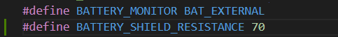
バッテリー残量確認の合成抵抗値
詳しくはハードウェア編の配線図を確認してください。
テスターでバッテリーの出力電圧を図りながら調整するといいかもしれません。
※本記事と同じkパーツ構成、抵抗値ならESP32miniは75、M5stampC3は70
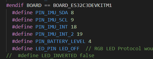
IOピンの定義
モジュールによってSCL、SDAの割り当てが違う場合があります。
お使いのモジュールの仕様を確認し割り当ててください。
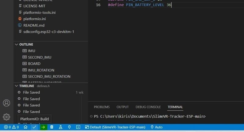
⑤platformio.ini、defines.hの編集、コピペが完了したらいよいよFWのアップロードです。電源スイッチはOFFのままUSBケーブルでESP32mini/M5stamp C3をPCに接続する。この時デバイスの接続音が鳴らない場合ケーブルやUSBポートを変えてみる。
下の青いバー(platformIO)の矢印→ボタンをクリックしてビルド&書き込みを行います。
書き込みが完了するとSUCCESSと表示されます。USBケーブルを外してください。
ここまででFWの書き込みは完了です。
※ESP32miniはmicroUSBなので充電専用ケーブルに注意。通信用を使用しましょう
※USBドライバはSlimeVRインストール時に導入済みを前提とします。

エラーが出る場合
エラー1 コードを間違えている可能性があります。特にIMUの記載部分など確認しましょう
エラー2 USBが正しく接続されていない可能性があります。USBケーブルを変える、ポートを変えてみてください。
また、slimeVRが起動している状態では通信中の為書き込みができません。
SlimeVRServerの設定
SlimeVRServerを起動します。
①言語設定
設定の一番下へスクロールすると言語設定があり日本語に変更できます。

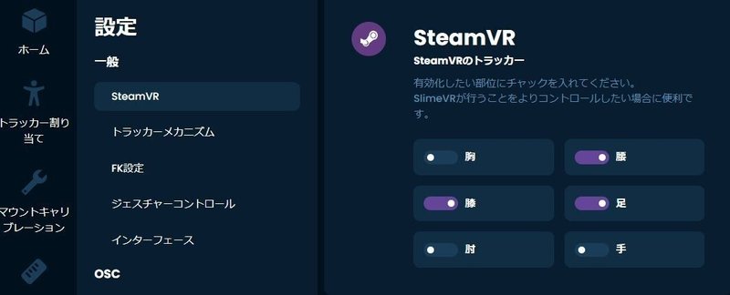
②SteamVRにトラッカーを追加する
設定のSteamVRのトラッカーの項目で必要に応じて
チェックを入れてください。
下半身5点の場合は足、膝、腰
③トラッカーのWiFi接続設定
トラッカーをUSBケーブルでPCに接続してください。接続時にセットアップしますかと出ますが無視してください。
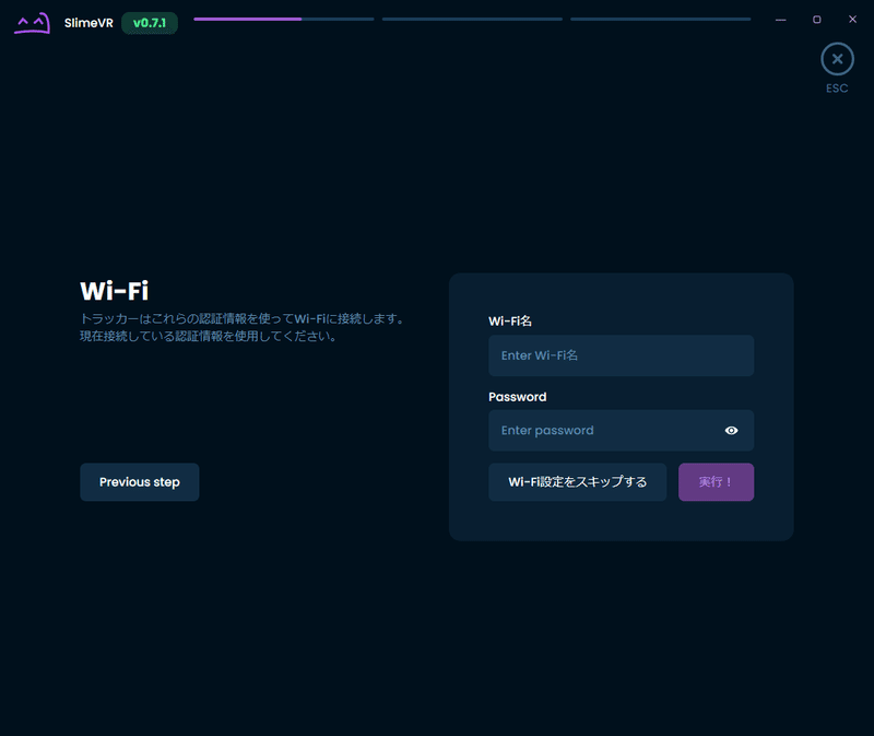
セットアップウィザードからセットアップ開始を行う。
使用しているWiFiのSSIDとパスワードを入力してください。
この時入力するSSIDは2.4Ghzになります。5Ghzは使用できません。
入力後実行を押すとWiFi設定が書き込まれます。USBケーブルを取り外して電源スイッチをONにしてください。
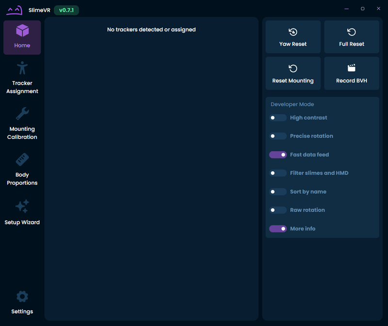
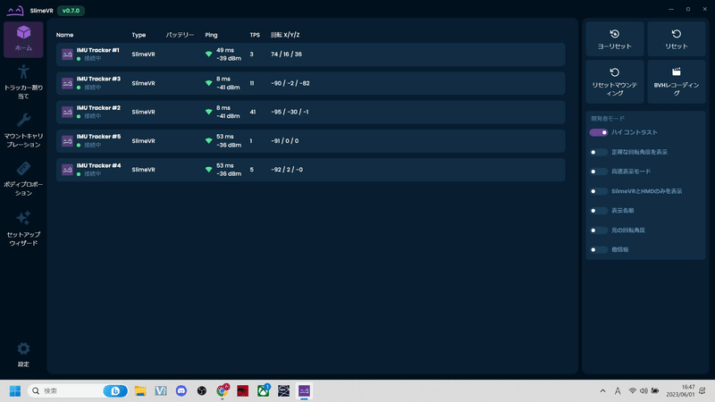
ホームにトラッカーが表示されます。
※例えばエレコムのルーターなどは2.4Ghz、5Ghz兼用のSSIDですがそのまま入力してかまいません。
※WiFiルーターがAPモード/BRモードになっていることを確認しましょう。
WiFiルーターがRTモードになっていてNTTなどのHGW(ひかり電話ルーター/光BBユニット等)にPCが接続されていると二重ルーターの影響によりトラッカーがSlimeVRServerに表示されない可能性があります。
※2.4Ghzの接続台数に注意しましょう。接続が不安定になっている場合はSSIDを増やすかWiFiルーターを増設してみてください。

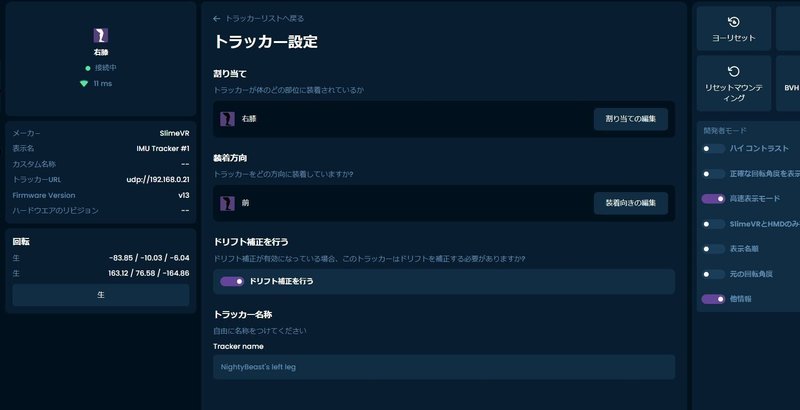
④トラッカーの割り当て
5点分のWiFi設定が完了した状態です。トラッカーが回転すると画面上のIMUトラッカーが紫枠で反応します。
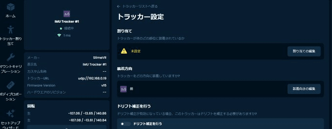
IMUTracker#〇をクリックしてトラッカー設定に進んでください。
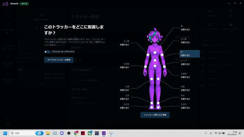
ビックリマークで未設定になっています。割り当ての編集をクリック。
任意の部位に割り当ててください。
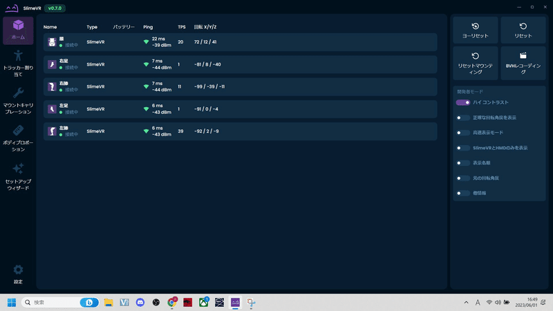
全てのトラッカーを割り当てた状態。ここまででトラッカーの設定は完了です。
SteamVR
SteamVRのインストール、Quest2、Pico4の接続は済んでいる前提で進めます。
SlimeVRServerとトラッカーの接続が済んでいる状態でHMDをPCに接続してください。トラッカーは各部位にベルトで固定してください。
Oculusの方はOculusLINK、Pico4の方はStreamingAssistantからSteamVRを起動。
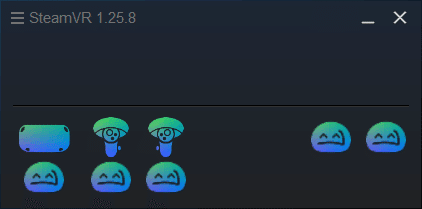
①SteamVRを起動
起動後にHMDとコントローラー、slimeVRが表示されると思います。
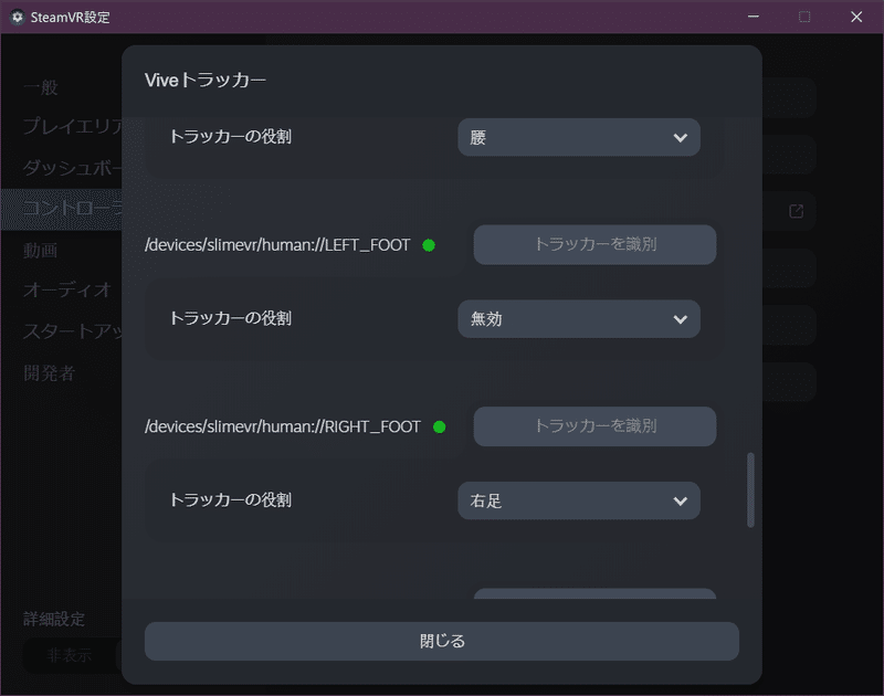
②SteamVRトラッカーの割り当て
SteamVR設定のコントローラからトラッカーの管理をクリック
SlimeVRトラッカーの役割が無効になっているのでそれぞれ割り当てる
完了したらSteamVRを一旦再起動してください。
ここまで出来たら後はキャリブレーションするだけです。

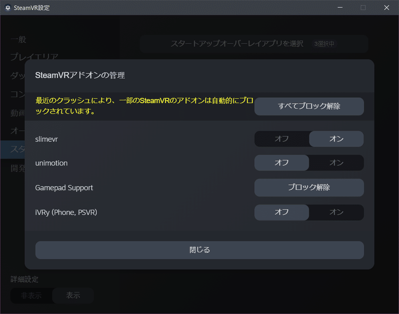
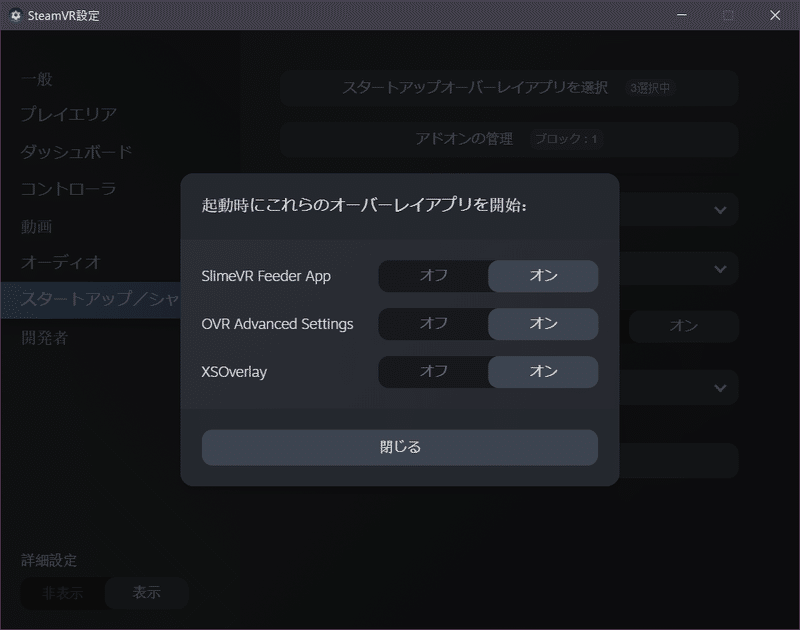
表示されない場合
SteamVRのスタートアップ/アドオンの設定よりSlimeVRとSlimeVRFeederAppがオンになっているか確認してください。
キャリブレーション
基本的にHMDをPC接続→SteamVR起動→SlimeVRでキャリブレーション→VRchat等でキャリブレーションという流れになります。
キャリブレーションをするまでにSlimeVR起動、トラッカーの電源オン、HMDのPC接続、SteamVRの起動まで完了している状態とします。
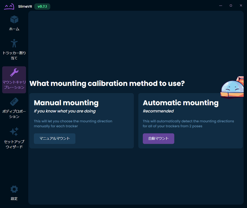
①マウントキャリブレーションを選択
自動マウントを選択します
②直立
直立で足は広げず、手を広げた状態でリセットします

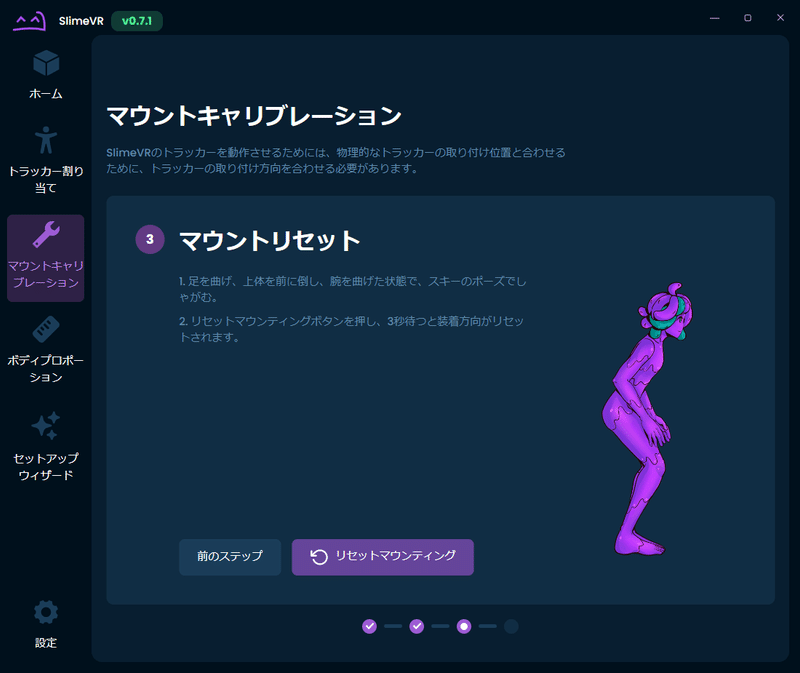
③しゃがみ
次に少ししゃがみ図のような状態でリセットマウンティングを行います。
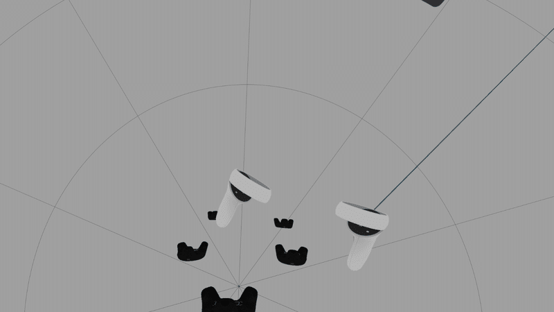
キャリブレーションが完了するとVR内のトラッカーははこのようになります
SteamVRからVRchatを起動してください
④VRChatのメニューからFBTを選択
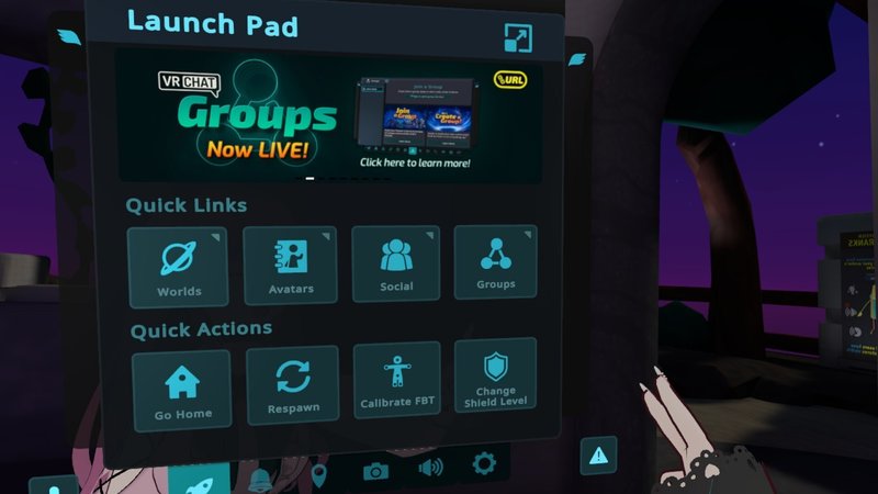
⑤キャリブレーションを行う
トラッカーが表示されるので体に合わせてコントローラーのトリガーを引く

ここまでお疲れさまでした。フルトラができるようになりました!!
SlimeVRですがSteamVR対応のVRSNS(Cluster、NeosVR等)であれば使用可能です
その他
足が埋まる、浮く、HMDとトラッカーの位置がかなりズレる。
足が埋まる、浮くに関してはSlimeVRの再起動やSteamVRのルームセットアップを行う、VRchatの身長の設定を変更するなどしてみてください。
HMDとトラッカーの位置がかなりズレるに関してはSlimeVRServerのHome画面にてお使いのHMDが表示されるのでトラッカーの割り当て⇒詳細な割り当て⇒頭にしてキャリブレーションを行うと改善する可能性があります。
トラッカーがドリフトしてきた場合
IMUセンサーのみなので時間が経つと体が捩れることがあります。
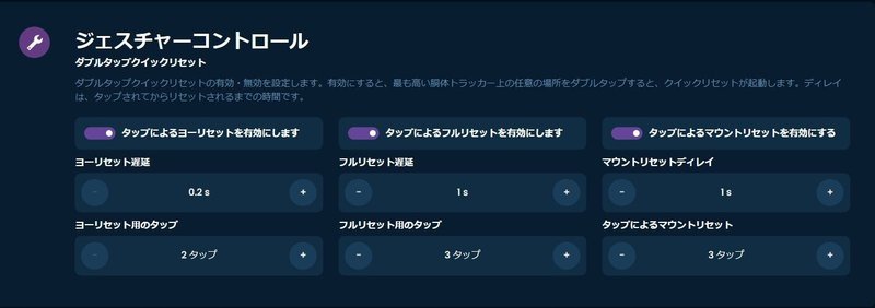
SlimeVRのホーム画面右のreset/quickresetで治りますが一々画面出すのも大変です。ジェスチャーコントロールがあるので活用しましょう。
こちらを有効にしておくと腰トラッカーを素早く揺らすことで
resetすることができます。
コントローラーに割り当てる場合
SlimeVRServerのリセット、ヨーリセットはショートカットキーがあるので
HMDのコントローラーキーバインドに割り当てが可能です。詳しくはドキュメントに記載されています。
公式ドキュメント
https://docs.slimevr.dev/server/setting-reset-bindings.html
キーバインドチュートリアル
ドリフト補正機能
MPU系BMI系センサー向けにドリフト補正機能があります。
こちらを有効にしておくと安価なセンサーでもreset回数を少なくすることができます。
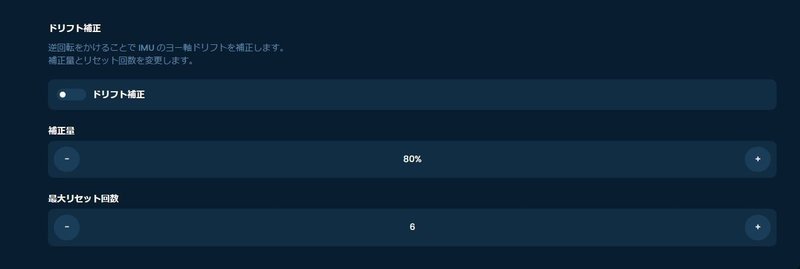
各トラッカーの設定でドリフト補正を行うチェックも忘れずに
まとめ
少し長くなりましたが、以上がSlimeVR、自作トラッカーセットアップとなります。複雑なように思えますが、意外とやってみると簡単に出来ます。安価にフルトラッキングを体験することができるのでVRが好き工作の好きな方にお勧めします!自分で作ることによってハードへの理解が深まりますしトラブル解決能力も上がります。なのはは今後も他のデバイスの作成等行いNoteに纏めていきたいです!
余談ですが、QUETSIDE経由でOculusにSlimeVRServerを入れてスタンドアローンでフルトラすることもできますが、需要があれば記事にしたいと思います。
最後まで購読頂きありがとうございました。
TwitterのフォローYoutubeチャンネルのフォロー大歓迎です。今後ともよろしくお願いします。
この記事が気に入ったらサポートをしてみませんか?